Configuration, Input capture 0-1, Chapter 36 input capture 3.configuration – FUJITSU MB91460 SERIES FR60 User Manual
Page 764
748
Chapter 36 Input Capture
3.Configuration
3. Configuration
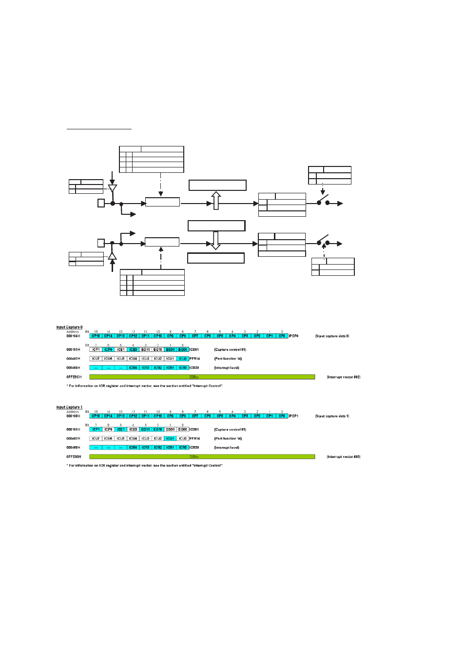
Figure 3-1 Configuration Diagram
Figure 3-2 Register List
Note: For information about ICR registers and interrupt vectors, see “
Input capture 0-1
TCDT
Free-run timer 0
Capture data register 0
1
0
IPCP0 (CP15-CP0)
Edge detection circuit
ICU0 / P14.0
P14 PFR: bit 0
0
1
GP Port
ICU input
From port
data register
From port
data register
Capture
EG01-00
ICS01:bit 1-0
No edge detection
0
0
1
1
0
1
1
0
Rising edge detection
Falling edge detection
Both edges detection
Edge detection polarity
Edge detection polarity
ICE0
ICS01:bit 4
0
1
Disable interrupts
Enable interrupts
ICP0
ICS01:bit 6
0
1
Interrupt request not present
Interrupt request present
WRITE 0: Flag clear
Input capture 0
Interrupt (#92)
Capture data register 1
1
0
Input capture 1
Interrupt (#93)
IPCP1 (CP15-CP0)
Edge detection circuit
ICU1 / P14.1
P14 PFR: bit 1
0
1
GP Port
ICU input
Capture
EG11-10
ICS01: bit 3-2
No edge detection
0
0
1
1
0
1
1
0
Rising edge detection
Falling edge detection
Both edges detection
ICE1
ICS01:bit 5
0
1
Disable interrupts
Enable interrupts
ICP1
ICS01:bit 7
0
1
Interrupt request not present
Interrupt request present
WRITE 0: Flag clear
0
0
1
1
0
1
1
0
0
0
0
0
0
1
1
0
0
0
Port read
Port read