2 tbcr: timebase timer control register – FUJITSU MB91460 SERIES FR60 User Manual
Page 174
158
Chapter 10 Standby
4.Registers
• Bit0: Main clock oscillation halt
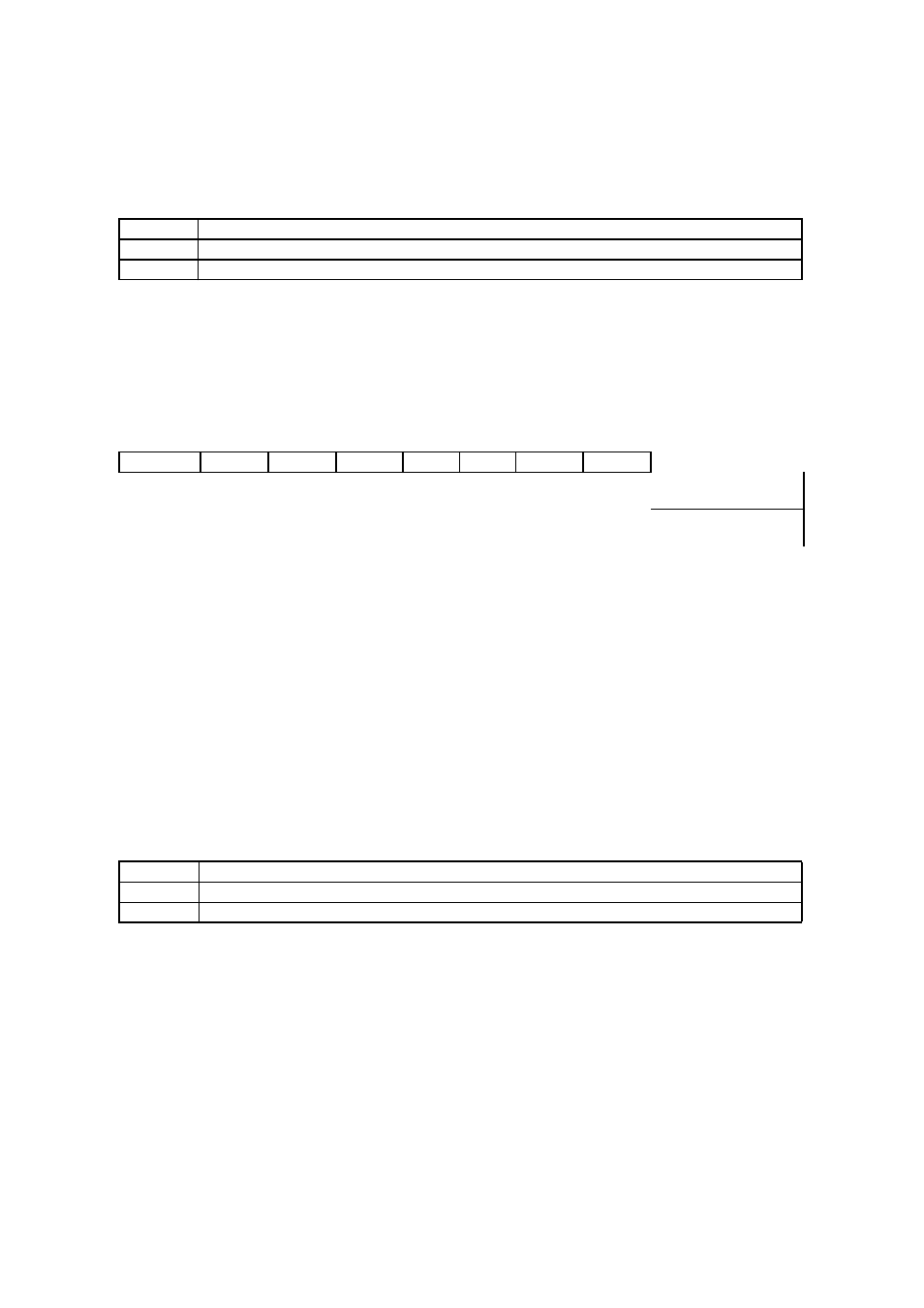
4.2 TBCR: Timebase timer control register
This register controls the timebase timer interrupts and the options for resets and standby
operation.
Note: See also “
Chapter 19 Timebase Timer (Page No.263)
• TBCR: Address 0482h (Access: Byte)
Meaning of Bit Attribute Symbols (Page No.10)
” for details of the attributes.)
• Bit7: Interrupt request flag for timebase timer
• This flag goes to “1” when a timebase timer interrupt request occurs
• Bit6: Interrupt request enable for the timebase timer
• Writing “1” to this bit enables timebase timer interrupt requests.
• Bit5-3: Interval time selection for timebase timer
•
Writing a value in the range “000”-“111” to these bits selects the interval time for the timebase timer.
(
F x
2
11
, x
2
12
, x
2
13
,
x
2
22
, x
2
23
,
x
2
24
,
x
2
25
,
x
2
26
)
• Bit2: Reserved
Writing does not affect the operation. The read value is undefined.
• Bit1: Enable synchronous reset operation
• Selects a normal reset “0” or a synchronous reset “1”.
• Bit0: Enable synchronous standby operation
OSCD1
Operation of main clock during stop mode
0
Continue oscillation
1
Halt oscillation
7
6
5
4
3
2
1
0
bit
TBIF
TBIE
TBC2
TBC1
TBC0
---
SYNCR
SYNCS
0
0
X
X
X
X
0
0
Initial value (INIT pin,
watchdog)
0
0
X
X
X
X
X
X
Initial value (Software
reset)
R(RM1),W
R/W
R/W
R1,W
R/W
RX/WX
RX/WX
R/W
Attribute
SYNCS
Operation
0
Normal reset operation (Not permitted on this model).
1
Enable synchronous standby operation (always set this before changing to a standby mode).