FUJITSU MB91460 SERIES FR60 User Manual
Page 656
640
Chapter 32 USART (LIN / FIFO)
5.USART Interrupts
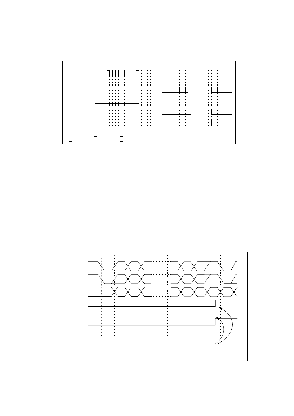
Figure 5-1 Bus idle interrupt generation
5.1 Reception Interrupt Generation and Flag Set Timing
The following are the reception interrupt causes: Completion of reception (SSR04: RDRF) and occurrence of a
reception error (SSR04: PE, ORE, or FRE).
■
Reception Interrupt Generation and Flag Set Timing
Generally a reception interrupt is generated, if the received data is complete (RDRF = 1) and the Reception
Interrupt Enable (RIE) flag bit of the Serial Status Register (SSR04) was set to "1". This interrupt is generated
if the first stop bit is detected in mode 0, 1, 2 (if SSM = 1), 3, or the last data bit was read in mode 2 (if SSM =
0).
(Note)
If a reception error has occurred, the Reception Data Register (RDR04) contains invalid data in each
mode.
Figure 5-2 Reception operation and flag set timing
(Note)
The example in figure
does not show all possible reception options for mode 0 and 3. Here it is:
Transmission
data
Reception
data
: Start bit : Stop bit : Data bit
TBI
RBI
Reception IRQ
Receive data
(mode 0/3)
Receive data
(mode 1)
Receive data
(mode 2)
ST: Start Bit SP: Stop Bit A/D: Mode 1 (multi processor) address/data selection bit
ST D0 D1 D2 .... D5 D6 D7/P SP ST
ST D0 D1 D2 .... D6 D7 A/D SP ST
D0 D1 D2 .... D4 D5 D6 D7 D0
RDRF
PE*, FRE
* The PE flag will always remain “0” in mode 1 or 3
reception interrupt occurs
ORE**
(if RDRF = "1")