Chapter 13 clock control, Overview, Features – FUJITSU MB91460 SERIES FR60 User Manual
Page 205: See also
189
Chapter 13 Clock Control
1.Overview
Chapter 13 Clock Control
1. Overview
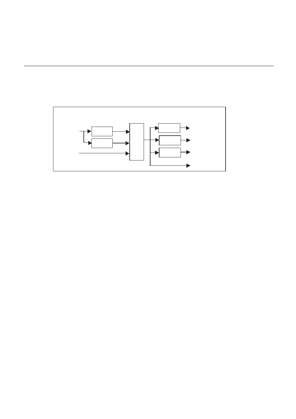
The clock control circuit consists of the source oscillator, base clock generator, and operating clock generator.
The circuit supports a range of clock speeds from the high speed clock (100MHz maximum) to the low speed
clock (32.768kHz).
2. Features
■
Source oscillation
• Main clock (F
CL-MAIN
): 4MHz
Input from the X0/X1 pins and used as the high speed clock
• Subclock (F
CL-SUB
): 32.768kHz
Input from the X0A/X1A pins and used as the low speed clock
• Subclock (F
CL-SUB
): 100kHz
RC oscillator and used as the low speed clock
■
Base clock (F): Selectable from 3 different clocks
• Main PLL (programmable) : F
CL-MAIN
x (MxN)\M
• Main clock divided by 2
: F
CL-MAIN
divided by 2
• Subclock
: F
CL-SUB
■
Operating clocks: Selectable from 16 different speeds
• CPU clock (CLKB): F/1, /2, /3, /4, /5, /6, /7, /8, ..., /16
The clock used by the CPU, internal memory, and internal buses. The circuits that use this clock are as
follows.
• CPU, internal RAM, internal ROM, bit search module,
• I bus, D bus, F bus, X bus
• On-chip debug support unit (DSU)
• Peripheral clock (CLKP): F/1, /2, /3, /4, /5, /6, /7, /8, ..., /16
The clock used by the peripheral functions and peripheral bus. The circuits that use this clock are as
follows.
• Peripheral bus
• Clock controller (bus interface unit only)
• Interrupt controller
• I/O ports
• External interrupt inputs, UART, 16-bit timer, and similar peripheral functions
Source oscillation
Base clock generator
Operating clock generator
Selector
Divider
Main clock
(source oscillation)
Sub clock
(source oscillation)
Divide by 2
PLL
Divider
Divider
CPU clock
Peripheral clock
External bus clock
Base clock