3 pwm1&2 compare registers – FUJITSU MB91460 SERIES FR60 User Manual
Page 892
876
Chapter 43 Stepper Motor Controller
2.Registers
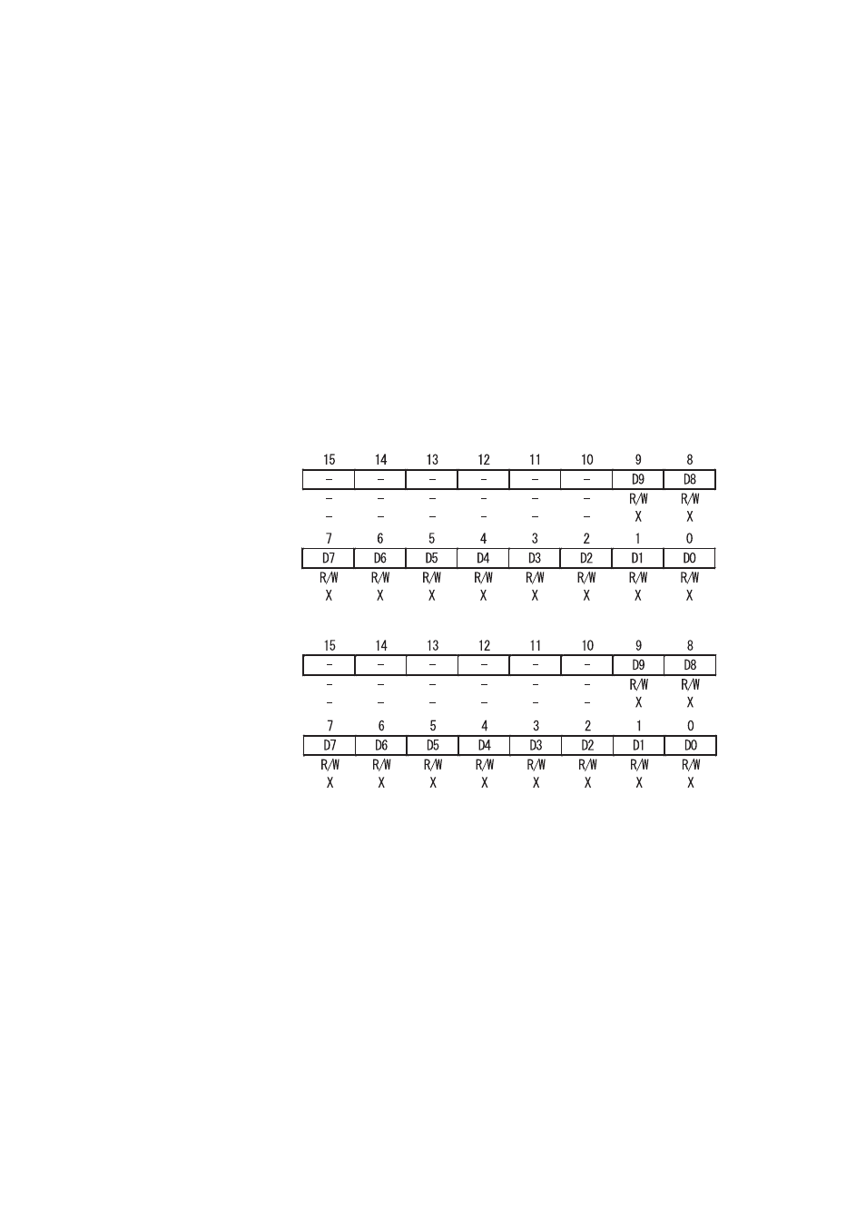
2.3 PWM1&2 Compare Registers
The value of the two 8(10) bits compare register of PWM1&2 determine the width of the PWM
pulse. The stored "00
H
(000
H
)" value indicates that the PWM duty is 0%, and the stored "FF
H
"
("3FF
H
") value indicates that the PWM duty is 99.6% (99.9%).
■
PWM1&2 Compare Registers
The PWM1&2 compare registers can be accessed at any time, but the changed value is reflected in the pulse
width at the end of the current PWM cycle after "1" is set to the BS bit of the PWM2 selection register.
When "0" is set to SC bit of the PWM control register, and PWM performs 8-bit operation, the D9 and D8 bits are
undefined value.
Be sure to perform half-word access to the PWM1&2 compare registers
[bit 15 to 10] Reserved bit
Always set the reserved bit to "0".
[bits 9 to 0] D9 to D0: Compare data
These bits are used to set the PWM pulse width.
PWM2 Compare register (PWC20, PWC21, PWC22, PWC23
, PWC24, PWC25
)
Address
Address
Address
Address
PWM1 Compare register (PWC10, PWC11, PWC12, PWC13, PWC14, PWC15)
0x092, 0x09A
0x0A2, 0x0AA
0x0B2, 0x0BA
0x093, 0x09B
0x0A3, 0x0AB
0x0B3, 0x0BB
0x090, 0x098
0x0A0, 0x0A8
0x0B0, 0x0B8
0x091, 0x099
0x0A1, 0x0A9
0x0B1, 0x0B9