Setting, Q & a, 2 how do i set int pin as the input – FUJITSU MB91460 SERIES FR60 User Manual
Page 344
328
Chapter 25 External Interrupt
6.Setting
6. Setting
Note: For the setting procedure, refer to the section indicated by the number.
7. Q & A
7.1 What are the types and setting procedures of detect levels?
There are 4 types of detect levels: “L” level, “H” level, rise, and fall
Carry out in Detection level bit (ELVR0. LBx, LAx) x = 0-7, and (ELVR1. LBx, LAx) x = 8-15.
7.2 How do I set INT pin as the input?
Use data direction registers (DDR22, DDR23, DDR24).
Use port function register (PFR22, PFR23, PFR24).
Remark: Even though the external interrupt can be even used with setting DDR=0 and PFR=0 (general
purpose port input mode), the input line will be disabled when setting STOP mode with HIZ.
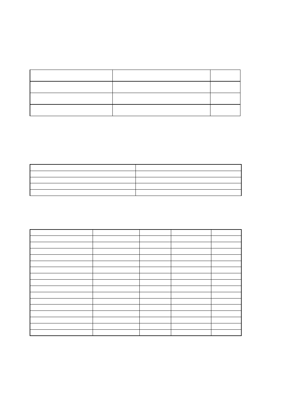
Table 6-1 Setting Required in Order to Use External Interrupts
Setting
Setting Registers
Setting
Procedures
*
Setting of detect level
External interrupt request level setting register
(ELVR0 - ELVR1)
See 7.1
Set INT pin as the input.
Data direction register (DDR22, DDR23, DDR24)
Port function register (PFR22, PFR23, PFR24)
See 7.2
External interrupt
External inputs
→Inputs the signal to INT0 - INT15 pins.
–
Operation mode
Detection level bit (LBn, LAn) n = 0-15
Use as “L” level detection
Sets to “00”
Use as “H” level detection
Sets to “01”
Use as rise detection
Sets to “10”
Use as fall detection
Sets to “11”
Operation
Data Direction bits
Setting
Port Function bit
Setting
To use INT0 pin input
DDR24.0
Set to “0”
PFR24.0
Set to “1”
To use INT1 pin input
DDR24.1
Set to “0”
PFR24.1
Set to “1”
To use INT2 pin input
DDR24.2
Set to “0”
PFR24.2
Set to “1”
To use INT3 pin input
DDR24.3
Set to “0”
PFR24.3
Set to “1”
To use INT4 pin input
DDR24.4
Set to “0”
PFR24.4
Set to “1”
To use INT5 pin input
DDR24.5
Set to “0”
PFR24.5
Set to “1”
To use INT6 pin input
DDR24.6
Set to “0”
PFR24.6
Set to “1”
To use INT7 pin input
DDR24.7
Set to “0”
PFR24.7
Set to “1”
To use INT8 pin input
DDR23.0
Set to “0”
PFR23.0
Set to “1”
To use INT9 pin input
DDR23.2
Set to “0”
PFR23.2
Set to “1”
To use INT10 pin input
DDR23.4
Set to “0”
PFR23.4
Set to “1”
To use INT11 pin input
DDR23.6
Set to “0”
PFR23.6
Set to “1”
To use INT12 pin input
DDR22.0
Set to “0”
PFR22.0
Set to “1”
To use INT13 pin input
DDR22.2
Set to “0”
PFR22.2
Set to “1”
To use INT14 pin input
DDR22.4
Set to “0”
PFR22.4
Set to “1”
To use INT15 pin input
DDR22.6
Set to “0”
PFR22.6
Set to “1”