10 refresh control register (rcr), Table 2-26 – FUJITSU MB91460 SERIES FR60 User Manual
Page 554
538
Chapter 31 External Bus
2.External Bus Interface Registers
2.10 Refresh Control Register (RCR)
This section describes the bit configuration and functions of the refresh control register (RCR).
■
Structure of the Refresh Control Register (RCR)
The refresh control register (RCR) is used to make various refresh control settings for SDRAM.
The setting of this register is meaningless as long as SDRAM control is not set for any area, in that case the
register value must not be updated from the initial state.
When read by a Read - modify - Write instruction, the SELF, RRLD, and PON bits always return to 0.
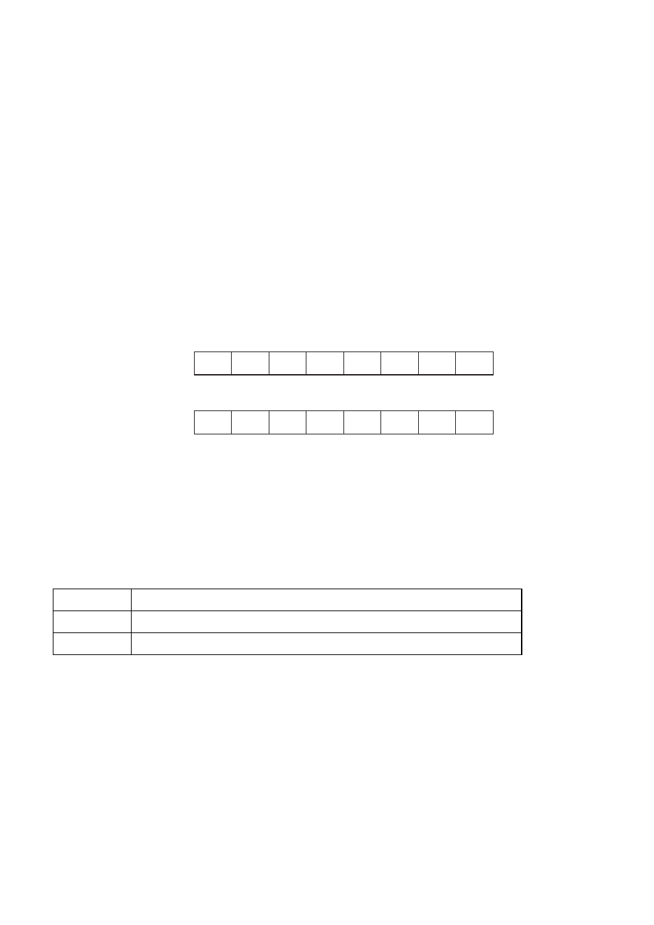
shows the bit configuration of the refresh control register (RCR).
Figure 2-10 Structure of the Refresh Control Register (RCR)
■
Bit Functions of the Refresh Control Register (RCR)
The following summarizes the functions of individual bits in the refresh control register (RCR).
[Bit 31] SELF (SELF refresh assert): Self - refresh control
This bit is used to control the self - refresh mode for memory that supports the self - refresh mode.
Table 4.2-42 lists the settings for self - refresh control.
Setting the bit to 1 performs a self - refresh after issuing the SELF command. Writing 0 terminates the self -
refresh mode.
To hold the contents of SDRAM when putting the LSI into stop mode, use this bit to enter the self - refresh mode
before entering the stop mode. At this time, centralized refreshing is performed before transition to the self -
refresh mode. External access requests generated before it is completed are put on hold. The mode transits to
the stop mode.
The device is released from the self - refresh mode either when 0 is written to this bit or access to SDRAM
occurs. At this time, centralized refreshing is performed immediately after the release. If external access such as
SDRAM access is attempted, therefore, the external access request is kept on hold and the CPU stops operation
for a while. An attempt to put the LSI into the stop mode when it cannot enter the self - refresh mode causes it to
directly enter the power save mode, resulting in corruption of data in SDRAM.
Table 2-26 Settings for self - refresh control
SELF
Self - refresh control
0
Auto - refresh or power - down
1
Transition to self-refresh mode
RCRH
31
30
29
28
27
26
25
24
0000 0684
H
SELF
RRLD RFINT5 RFINT4 RFINT3 RFINT2 RFINT1 RFINT0
00XXXXXXB(INIT)
W/R
RCRL
0000 0685
H
BRST
RFC2
RFC1
RFC0
PON
TRC2
TRC1
TRC0
W/R
W/R
23
22
21
20
19
18
17
16
Address
Address
bit
bit
W/R
W/R
W/R
W/R
W/R
W/R
W/R
W/R
W/R
W/R
W/R
W/R
W/R
00XXXXXXB(RST)
XXXX0XXXB(INIT)
XXXX0XXXB(RST)
Initial value