Operation flowcharts – FUJITSU MB91460 SERIES FR60 User Manual
Page 389
373
Chapter 26 DMA Controller
4.Operation Flowcharts
4. Operation Flowcharts
This section contains operation flowcharts for the following transfer modes:
• Block transfer
• Burst transfer
• Demand transfer
■
Block Transfer
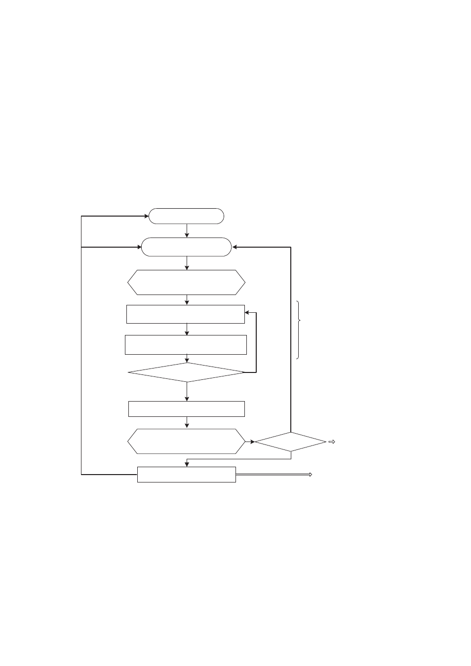
"Operation Flowchart for Block Transfer" shows the flowchart for block transfer.
Figure 4-1 Operation Flowchart for Block Transfer
■
Burst Transfer
"Operation Flowchart for Burst Transfer" shows the operation flowchart for burst transfer.
Load the initial address,
transfer count, and number
of blocks
Activation request
wait
Interrupt clear
DMA transfer end
DMA interrupted
BLK=0
DTC=0
DMA stop
DENB=1
DENB=>0
Write back the address,
transfer count, and
number of blocks
Number of blocks - 1
Activation request
One-time access for fly-by
Reload enable
Only when the peripheral
interrupt activation source
is selected
Calculate the address for
transfer source address access
Calculate the address for transfer
destination address access
Block transfer
- Can be activated by all activation sources (selection).
- Can access to all areas.
- The number of blocks can be set.
- Interrupt clear is issued when transfer of the specified
number of blocks is completed.
- The DMA interrupt is issued when transfer for the number
of times specified is completed.
Transfer count - 1
Interrupt cleared