Auto algorithms, 1 command operation, Running an auto algorithm. see – FUJITSU MB91460 SERIES FR60 User Manual
Page 1015
999
Chapter 54 Flash Memory
7.Auto Algorithms
7. Auto Algorithms
Writes and erases to Flash memory are performed by launching the Flash memory's own Auto Algorithms.
7.1 Command Operation
Auto Algorithms are launched by writing one to six half words (16 bits) to the Flash memory in succession.
This is called a “command.” Writing an illegal address or data, or writing them in the incorrect order, will reset
the Flash memory to read mode.
• Auto Algorithm Execution Status
If an Auto Algorithm is started in CPU mode, it is possible to learn the operational state of the Auto
Algorithm via the internal ready signal (RDY). The level of the ready signal can be read from the “RDY” bit
of the FLASH Memory Control Status Register.
While the “RDY” bit is set to “0”, data read is the hardware sequence flag indicating Flash memory status
(see Hardware sequence flag in (3) and (4)).
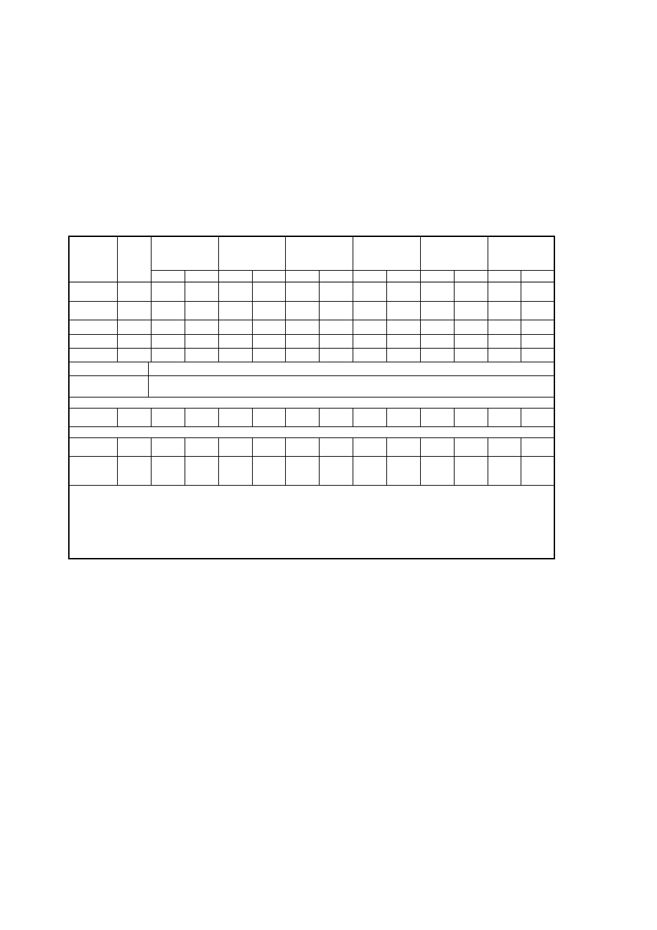
Table 7-1 List of Commands in CPU mode
Command
Sequence
Bus
Write
Cycle
1st Bus
Write cycle
2nd Bus
Write cycle
3rd Bus
Write cycle
4th Bus
Read/write
cycle
5th Bus
Write cycle
6th Bus
Write cycle
Address
Data
Address
Data
Address
Data
Address
Data
Address
Data
Address
Data
Read/
reset
1
*XXXX
H
F0
H
---
---
---
---
---
---
---
---
---
---
Read/
Reset
4
*x557
H
AA
H
*yAAF
H
55
H
*x557
H
F0
H
RA
RD
---
---
---
---
Writing
4
*x557
H
AA
H
*yAAF
H
55
H
*x557
H
A0
H
PA
PD
---
---
---
---
Chip erase
6
*x557
H
AA
H
*yAAF
H
55
H
*x557
H
80
H
*x557
H
AA
H
*yAAF
H
55
H
*x557
H
10
H
Sector erase
6
*x557
H
AA
H
*yAAF
H
55
H
*x557
H
80
H
*x557
H
AA
H
*yAAF
H
55
H
SA
30
H
Sector erase suspend
Suspend erase during sector erase with input of Address= “*XXXX
H
”, data = “B0
H
”
Sector erase resume
Resume erase after Sector erase suspend, with input of Address= “*XXXX
H
”, data = “30
H
”
Continuous
mode
3
*x557
H
AA
H
*yAAF
H
55
H
*x557
H
20
H
---
---
---
---
---
---
Continuous
writing
2
*XXXX
H
A0
H
PA
PD
---
---
---
---
---
---
---
---
Continuous
mode
Reset
2
*XXXX
H
90
H
*XXXX
H
F0
H
or
00
H
---
---
---
---
---
---
---
---
Both word mode and half-word mode are the same for commands. Any data can be set in the non-specified bits.
RA: Read address
PA: Write address
SA: Sector address (Specify any address in the sector)
RD: Read data
PD: Write data
*: “0004”, “0005”, “0006”, “0007”, “0008”, “0009”, “000A”, “000B”, “000C”, “000D”, “000E”, “000F”, “0010”, “0011”, “0012”, “0013” or “0014”
x: Any odd hex digit: “1“, “3“, “5“, “7“, “9“, “B“, “D“ or “F“
y: Any even hex digit: “0“, “2“, “4“, “6“, “8“, “A“, “C“ or “E“