2 operation in synchronous mode (operation mode 2) – FUJITSU MB91460 SERIES FR60 User Manual
Page 665
649
Chapter 32 USART (LIN / FIFO)
7.USART Operation
If transmission interrupt is enabled (TIE = 1), the interrupt is generated by the TDRE flag. Note, that the initial
value of the TDRE flag is "1", so that in this case if TIE is set to "1" an interrupt will occur immediately.
■
Reception Operation
Reception operation is performed every time it is enabled by the Reception Enable (RXE) flag bit of the
SCR04. If a start bit is detected, a data frame is received according to the format specified by the SCR04. By
occurring errors, the corresponding error flags are set (PE, ORE, FRE). However after the reception of the
data frame the data is transferred from the serial shift register to the Reception Data Register (RDR04) and
the Receive Data Register Full (RDRF) flag bit of the SSR5 is set. The data then has to be read by the CPU.
By doing so, the RDRF flag is cleared. If reception interrupt is enabled (RIE = 1), the interrupt is simply
generated by the RDRF.
Note: Only when the RDRF flag bit is set and no errors have occurred the Reception Data Register (RDR04)
contains valid data.
■
Stop Bit, Error Detection, and Parity
For transmission, 1 or 2 stop bits can be selected. During reception, if selected, both stop bits are checked, to
set the reception bus idle (RBI) flag of ECCR04 correctly after the second stop bit.
In mode 0 parity, overrun, and framing errors can be detected.
In mode 1, overrun and framing errors can be detected. Parity is not provided.
By setting the Parity Enable (PEN) bit of the Serial Control Register (SCR04) the USART provides parity
calculation (during transmission) and parity detection and check (during reception) in mode 0 (and mode 2 if
the SSM bit of ECCR04 is set).
Even parity is set, if the P bit of SCR04 is cleared, odd parity if the flag bit is set. In mode 1, overrun and
framing errors can be detected. Parity is not provided.
■
Signal mode NRZ and RZ
To set USART to the NRZ data format set the ECCR04:INV bit to 0 (initial value).
RZ data format is set, if the ECCR04:INV bit was set to 1.
7.2 Operation in Synchronous Mode (Operation Mode 2)
The clock synchronous transfer method is used for USART operation mode 2 (normal mode).
■
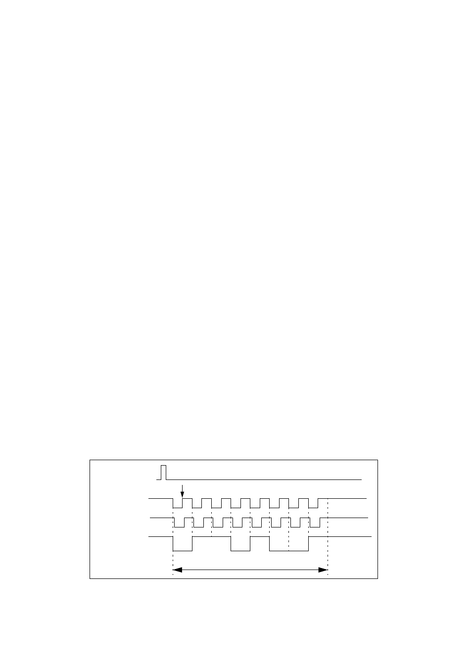
Transfer data format (standard synchronous)
In the synchronous mode, 8-bit data is transferred with no start or stop bits if the SSM bit of the Extended
Communication Control Register (ECCR04) is 0. A special clock signal belongs to the data format in mode 2.
The figure below illustrates the data format during a transmission in the synchronous operation mode
Figure 7-2 Transfer data format (operation mode 2).
Transmission data
writing
Transmitting or
receiving clock
Transmission and
reception data
0 1 1 0 1 0 0 1
Data
LSB
MSB
Mark level
(normal)
Transmitting
clock (SCDE = 1)
Mark level
Mark level
Reception data sample edge (SCES = 0)