Alarm comparator control/status register (acsr) – FUJITSU MB91460 SERIES FR60 User Manual
Page 934
918
Chapter 46 Alarm Comparator
3.Alarm Comparator Control/Status Register (ACSR)
3. Alarm Comparator Control/Status Register (ACSR)
• ACSR0 (ch0): Address 01AD
H
(Access:
Byte
)
• ACSR1 (ch1): Address 01AF
H
(Access:
Byte
)
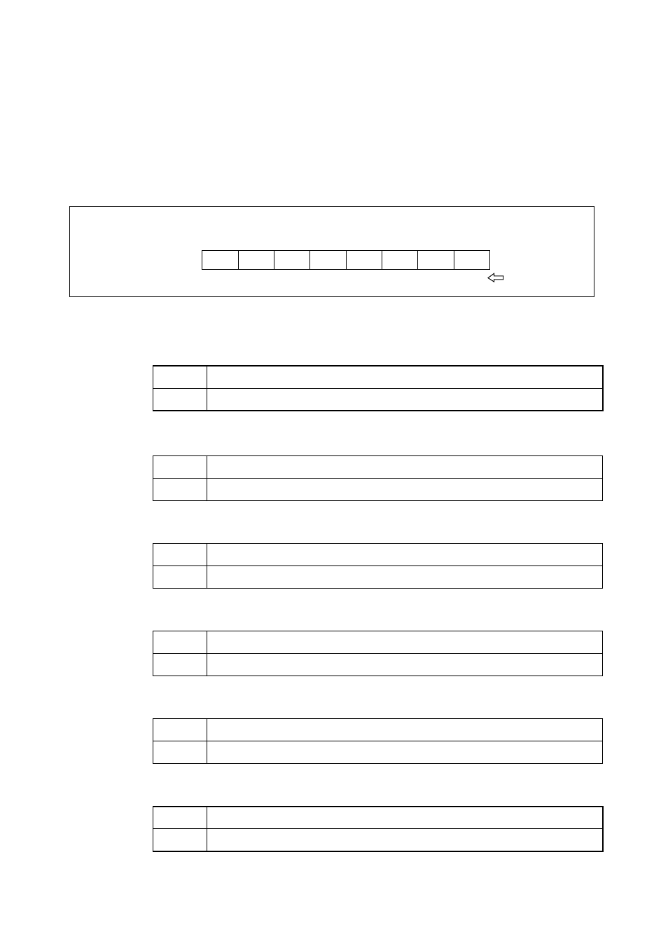
Figure 3-1 Structure of Alarm comparator control/status register
Bit 7: MD Mode select
Bit 6: OV_EN Overvoltage Enable
Bit 5: UV_EN Undervoltage Enable
Bit 4: OUT2 synchronized output of Alarm comparator UV output.
Bit 3: OUT1 synchronized output of Alarm comparator OV output.
Bit 2: IRQ Interrupt bit.
1
Fast mode enabled
0
Slow mode enabled
[Initial value]
1
Interrupt enabled in case of overvoltage. [Initial value]
0
No interrupt in case of overvoltage
1
Interrupt enabled in case of undervoltage
[Initial value]
0
No interrupt in case of undervoltage.
0
analog input voltage < 2/5 AVDD
1
analog input voltage > 2/5 AVDD
1
analog input voltage > 4/5 AVDD
0
analog input voltage < 4/5 AVDD
1
Under- or overvoltage condition detected
0
Normal operation
OUT2
4
OUT1
3
IRQ
2
IEN
1
PD
0
Initial value
011XXX00
B
MD
7
OV_EN
6
UV_EN
5
Address
Bits
R
R
R/W
R/W
R/W
Access
R/W
R/W
R/W
ACSR0 0000 01AD
H
ACSR1 0000 01AF
H