FUJITSU MB91460 SERIES FR60 User Manual
Page 226
210
Chapter 14 PLL Interface
4.Registers
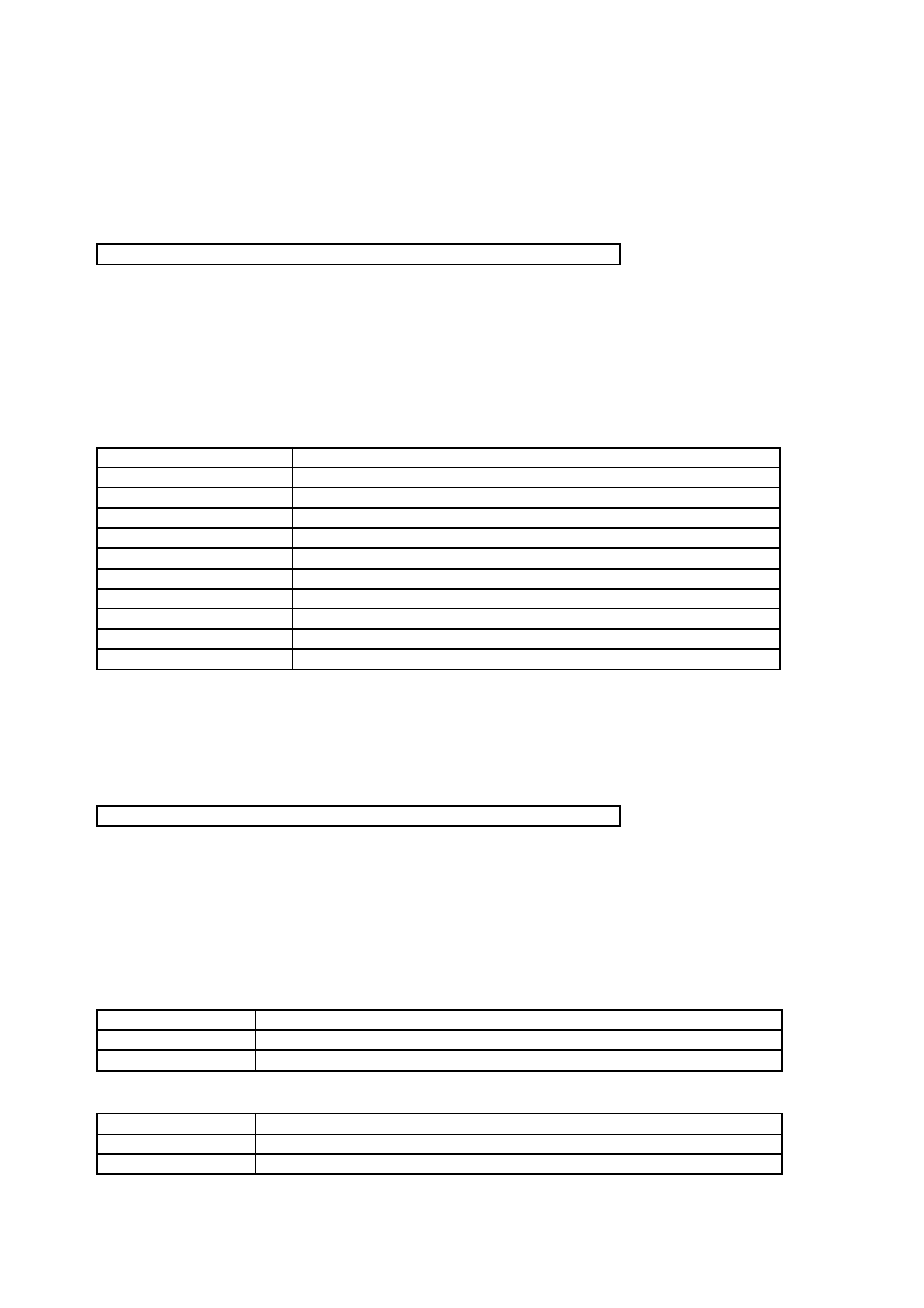
• PLLMULG: Address 048Fh (Access: Byte, Halfword, Word)
Meaning of Bit Attribute Symbols (Page No.10)
” for details of the attributes.)
• Bit7-6: Reserved bitThe read value is always “0”.
• Bit5-0: PLL auto gear divide-by-G step multiplier selection
(Note)
See chapter
for detailed information on how to use this function.
(Note)
The register value can not be changed once PLL is selected as clock source (CLKS[1:0]=”10”).
• PLLCTRL: Address 0490h (Access: Byte, Halfword, Word)
Meaning of Bit Attribute Symbols (Page No.10)
” for details of the attributes.)
• Bit7-4: Reserved bitThe read value is always “0”.
• Bit3: Interrupt Enable Gear DOWN.
• Bit2: Interrupt Flag Gear DOWN.
7
6
5
4
3
2
1
0
bit
MLG7
MLG6
MLG5
MLG4
MLG3
MLG2
MLG1
MLG0
0
0
0
0
0
0
0
0
Initial value (
INIT pin input,
watchdog reset
)
X
X
X
X
X
X
X
X
Initial value
(Software reset)
R/W
R/W
R/W
R/W
R/W
R/W
R/W
R/W
Attribute
MLG5-MLG0
Divide-by-G step multiplier
00000000
Divide-by-G step x 1 (multiply by 1)
00000001
Divide-by-G step x 2 (multiply by 2)
00000010
Divide-by-G step x 3 (multiply by 3)
00000011
Divide-by-G step x 4 (multiply by 4)
00000100
Divide-by-G step x 5 (multiply by 5)
00000101
Divide-by-G step x 6 (multiply by 6)
00000110
Divide-by-G step x 7 (multiply by 7)
00000111
Divide-by-G step x 8 (multiply by 8)
......
.....
11111111
Divide-by-G step x 256 (multiply by 256)
7
6
5
4
3
2
1
0
bit
-
-
-
-
IEDN
GRDN
IEUP
GRUP
0
0
0
0
0
0
0
0
Initial value (
INIT pin input,
watchdog reset
)
0
0
0
0
X
X
X
X
Initial value
(Software reset)
R/W
R/W
R/W
R/W
R/W
RM1/W
R/W
RM1/W
Attribute
IEDN
Function
0
Gear DOWN interrupt disabled [Initial value]
1
Gear DOWN interrupt enabled
GRDN
Function
0
Gear DOWN interrupt not active [Initial value]
1
Gear DOWN interrupt active