Register – FUJITSU MB91460 SERIES FR60 User Manual
Page 301
285
Chapter 21 Hardware Watchdog Timer
3.Register
3. Register
3.1 Hardware watchdog timer control and status register
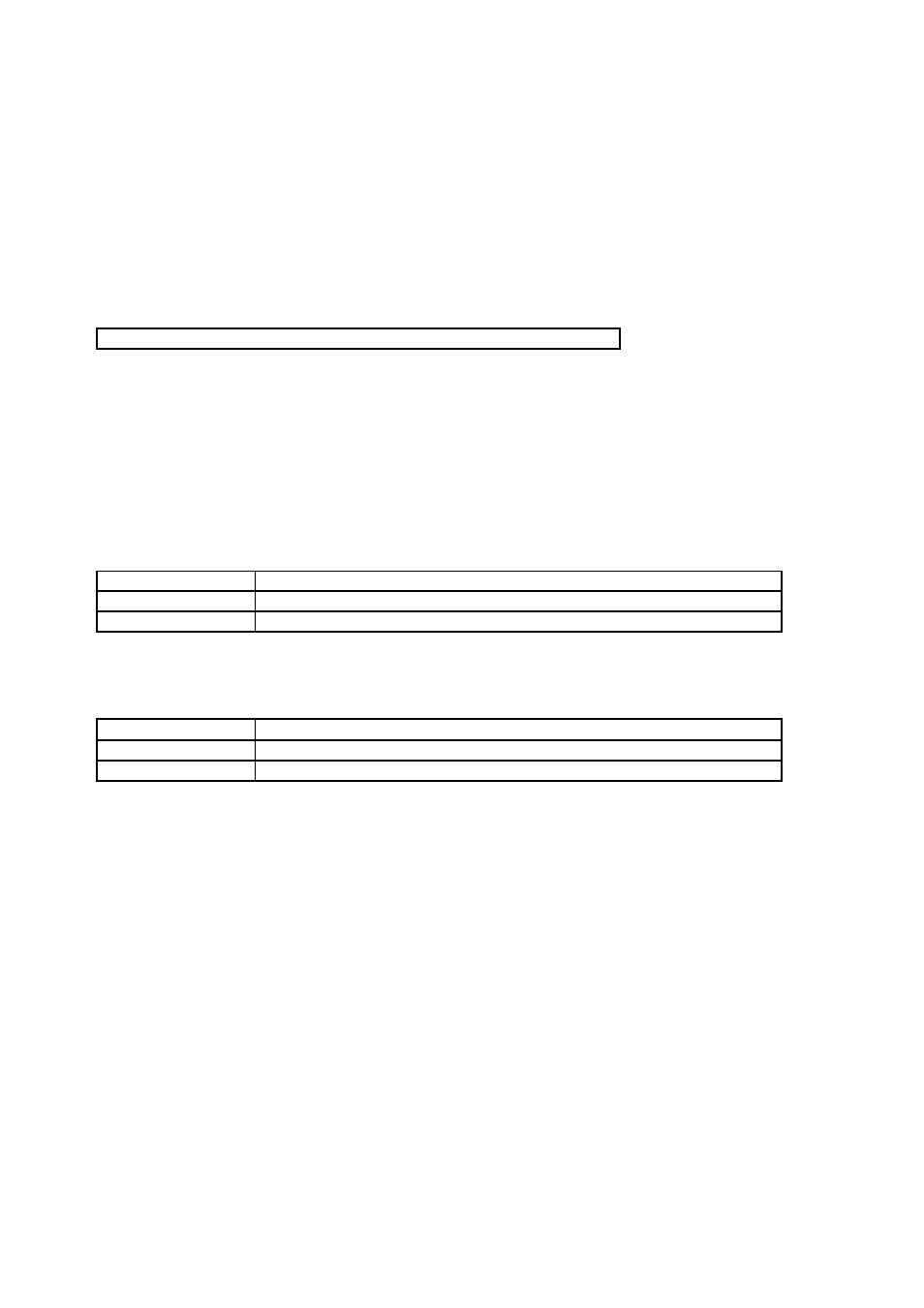
Hardware watchdog timer control status register (with reset flag and clear bit).
• HWWD: Address 04C7h (Access: Byte)
Meaning of Bit Attribute Symbols (Page No.10)
” for details of the attributes.)
• Bit7-5: Reserved bits. Always write “0” to these bits.
• Bit4: Reserved bit. Always write “1” to this bit.
• Bit3: CL (counter clear).
This bit is write only, it is always read as ‘1’.
• Bit2-1: Reserved bits. Always write “0” to these bits.
• Bit0: CPUF (CPU reset Flag).
This bit is initialized by external reset input (INITX) or clock supervisor reset, but not by internal reset.
Writing ‘0’ clears this bit, writing ‘1’ has no effect.
7
6
5
4
3
2
1
0
bit
RESV0
RESV0
RESV0
RESV1
CL
RESV0
RESV0
CPUF
0
0
0
1
1
0
0
0
Initial value (
INIT pin input,
watchdog reset
)
0
0
0
1
1
0
0
X
Initial value
(Software reset)
R/W0
R/W0
R/W0
R/W1
W
R/W0
R/W0
R/W
Attribute
CL
Function
0
By writing ‘0’ the watchdog timer is cleared
1
Writing ‘1’ has no effect
CPUF
Function
0
Watchdog reset not triggered
1
Watchdog reset triggered (overflow of watchdog timer occured)