Figure 4-2 – FUJITSU MB91460 SERIES FR60 User Manual
Page 390
374
Chapter 26 DMA Controller
4.Operation Flowcharts
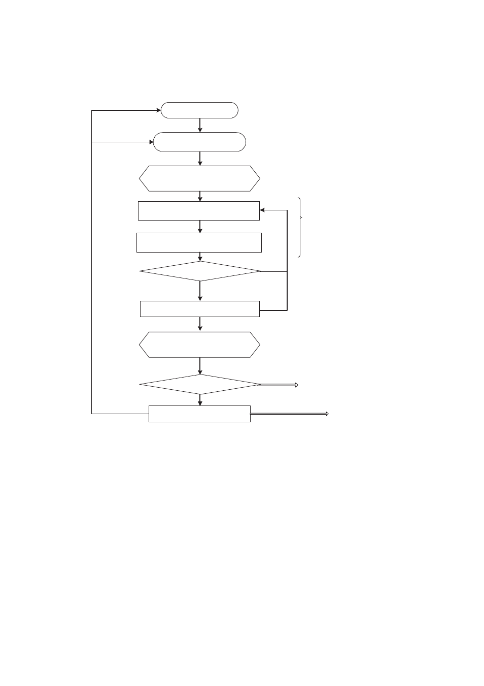
Figure 4-2 Operation Flowchart for Burst Transfer
■
Demand Transfer
"Operation Flowchart for Demand Transfer" shows the operation flowchart for demand transfer.
Load the initial address,
transfer count, and
number of blocks
Activation request
wait
DMA transfer end
DMA interrupted
BLK=0
DTC=0
DMA stop
DENB=1
DENB=>0
Write back the address,
transfer count, and number
of blocks
Number of blocks - 1
Interrupt clear
One-time access for fly-by
Reload enable
Only when the peripheral interrupt
activation source is selected
Calculate the address for
transfer source address access
Calculate the address for transfer
destination address access
Transfer count - 1
Interrupt cleared
Burst transfer
- Can be activated by all activation sources (selection).
- Can access to all areas.
- The number of blocks can be set.
- Interrupt clear and the DMA interrupt are issued when
transfer for the number of times specified is completed.
- XG Series P3NK-4452-01ENZD (614 pages)
- FPCAC14C (1 page)
- MCJ3230SS (161 pages)
- MBA3073NC (138 pages)
- T5140 (76 pages)
- T5140 (102 pages)
- MAM3367MC/MP (152 pages)
- MPC3045AH (185 pages)
- MB2142-02 (23 pages)
- MB15F86UL (6 pages)
- MHS2030AT (40 pages)
- MHW2100BS (296 pages)
- MHK2060AT (227 pages)
- Disk Drives MHK2060AT (227 pages)
- MCM3064SS (170 pages)
- Mainboard D1561 (45 pages)
- MHC2040AT (219 pages)
- D1961 (45 pages)
- DISK DRIVES MHM2100AT (231 pages)
- MHR2010AT (250 pages)
- MHZ2120BJ (320 pages)
- MCE3064AP (175 pages)
- LQFP-64P (16 pages)
- Solaris PCI GigabitEthernet 3.0 (115 pages)
- MAY2036RC (94 pages)
- MAB3091 (142 pages)
- MPE3XXXAT (191 pages)
- MHV2040AH (40 pages)
- MHW2040AC (278 pages)
- ETERNUSmgr P2X0-0202-01EN (64 pages)
- VSS Hardware Provider 2.1 (134 pages)
- MAG3182FC (61 pages)
- MAU3147NC/NP (130 pages)
- MAX3147RC (94 pages)
- MHV2160BT (296 pages)
- MHV2040AT (280 pages)
- MAW3300NC/NP (130 pages)
- DeskPower E623 (50 pages)
- MAG3182LC (133 pages)
- OPTICAL DISK DRIVES MDG3064UB (42 pages)
- MHF2021AT (225 pages)
- MHR2040AT (40 pages)
- Single Drive FTM7926FB (1 page)
- PG-FCS103 (98 pages)
- MAS3735FC (114 pages)