B-14, Figure b-14, Hi32 control register (hctr) – Motorola DSP56301 User Manual
Page 338: Host processor (hi32)
Programming Sheets
B
-26
DSP56301 User’s Manual
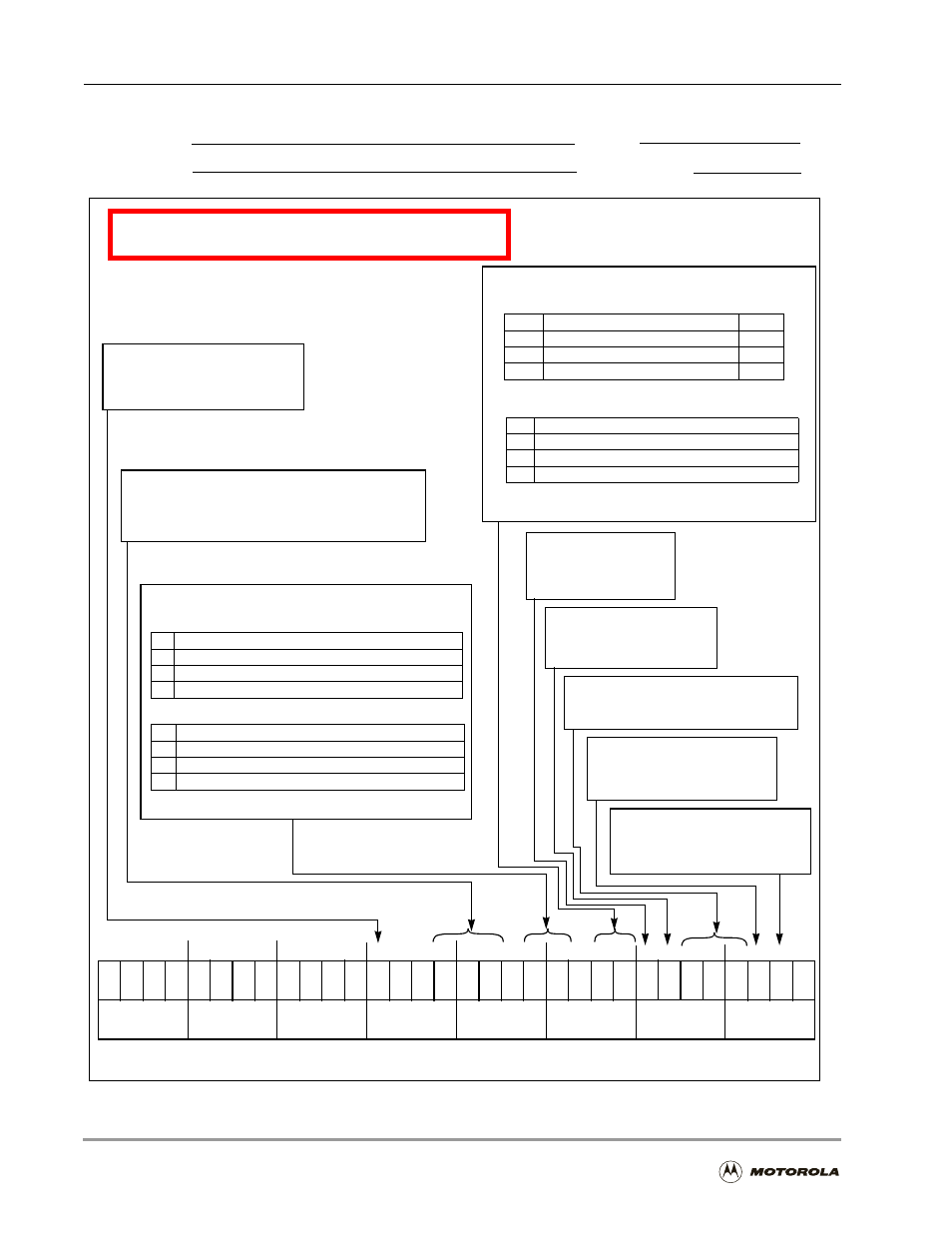
Figure B-14. HI32 Control Register (HCTR)
Host Processor (HI32)
HI32 Control Register (HCTR)
Reset = $00000000
15 14 13 12 11 10 9 8 7 6 5 4 3 2 1 0
19 18 17 16
23 22 21 20
0 = Fetch mode
1 = Pre-fetch mode
TWSD
Slave Fetch Type, Bit 7
Target Wait State Disable, Bit 19
0 = PCI wait states enabled
DMA Enable, Bit 6
Used for host-to-DSP communication
Set or cleared by host, visible to DSP
Host Flags, Bits 5–3
1 = PCI wait states disabled
*
= Reserved, Program as 0
*
0
*
0
Host Semaphores, Bits 16–14
Serve only as read/write repository for semaphores
Receive Request Enable, Bit 2
Read/Write
Application:
Date:
Programmer:
Sheet 5 of 10
*
0
27 26 25 24
31 30 29 28
*
0
*
0
*
0
*
0
*
0
*
0
*
0
*
0
*
0
*
0
*
0
*
0
*
0
*
0
HS2
HS1
HS0
HRF1 HRF0
HTF1 HTF0
SFT DMAE HF2
HF1
HF0 RREQ TREQ
when multiple master hosts are used.
Modes: PCI only
Modes: UBM and PCI
Host Receive Data Transfer Format, Bits 12–11
00
32-bit data mode
01
3 LSBs in DTXS/HRXS right-aligned/zero extended to HAD[31–0] MSB
10
3 LSBs in DTXS/HRXS left-aligned /zero filled to HAD[31–0] LSB
11
3 LSBs in DTXS/HRXS right-aligned/sign extended in HAD[31–0] MSB
HI32 bus data transfer formats, as follows:
00
24-bit data mode: DTXS to HRXS and HD[23–0]
01
2 LSB data in DTXS to HRXS and HD[15–0]
10
2 LSB data in DTXS to HRXS and HD[15–0]
11
2 MSB data in DTXS to HRXS and HD[15–0]
DSP-to-UB Host (DCTR[HM] = $2 or $3)
DSP-to-PCI Host (DCTR[HM] = $1)
Note: LSB = least significant byte; MSB = most significant byte
Modes: UBM and PCI
Host Transmit Data Transfer Format, Bits 9–8
00
32-bit data mode
01
3 LSBs from HAD[23–0] to HTXR/DRXR LSBs
10
3 LSBs from HAD[23–0] to HTXR/DRXR LSBs
11
3 MSBs from HAD[31–8] to HTXR/DRXR LSBs
HI32 bus data transfer formats, as follows:
00
24-bit data mode: HD[23–0] to 3 LSBs HTXR/DRXR
01
HD[15–0] to 3 LSBs HRXS (right-aligned/zero extended) to DRXR
10
HD[15–0] to 3 LSBs HRXS (right-aligned/sign extended) to DRXR
11
HD[15–0] to 3 LSBs HRXS (left aligned/zero filled) to DRXR
UB Host-to-DSP (DCTR[HM] = $2 or $3)
PCI Host-to-DSP (DCTR[HM] = $1)
Note: LSB = least significant byte; MSB = most significant byte
Modes: UBM and PCI
Transmit Request Enable, Bit 1
0 = DMA accesses disabled
1 = DMA accesses enabled
0 = Receive requests disabled
1 = Receive requests enabled
0 = Transmit requests disabled
1 = Transmit requests enabled
Modes: UBM only
Modes: UBM only
Modes: UBM only
Modes: UBM and PCI
Note: Address insertion is affected the same way as the data in PCI mode.