3 using the encoder signal output, Encoder output signals divided – Yaskawa Large Capacity Sigma II Series User Manual
Page 98
4 Parameter Settings and Functions
4.2.3 Using the Encoder Signal Output
4-22
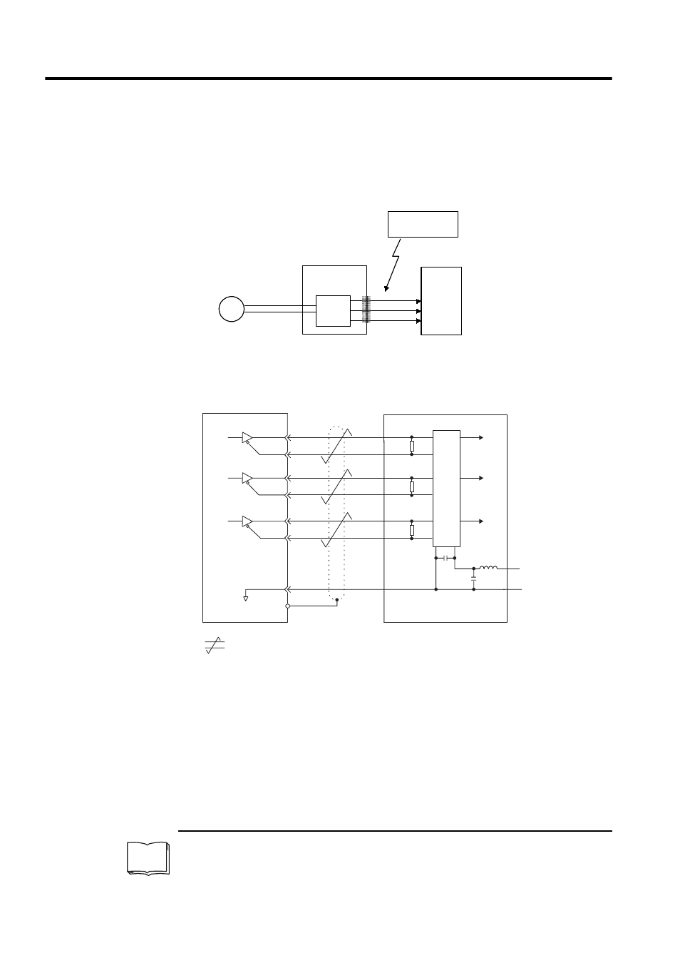
4.2.3 Using the Encoder Signal Output
Encoder output signals divided
1
inside the SERVOPACK can be output externally. These
signals can be used to form a position control loop in the host controller.
The output circuit is for line-driver output. Connect each signal line according to the follow-
ing circuit diagram.
1
Dividing
Dividing means converting an input pulse train from the encoder mounted on the servomotor accord-
ing to the preset pulse density and outputting the converted pulse. The units are pulses per revolution.
TERMS
Frequency
dividing
circuit
PG
SERVOPACK
CN2
CN1
(Servomotor)
Encoder
Host controller
These outputs
explained here.
Phase A
Phase B
Phase C
Serial data
Connector shell
Shield
SERVOPACK
Line receiver
Host controller
Phase
A
Phase
B
Phase
C
Choke
coil
Smoothing
capacitor
: represents twisted-pair wires.
Applicable line receiver: SN75175 manufactured
by Texas Instruments Inc., MC3486 or the equivalent.
R (terminator): 220 to 470
Ω
C (decoupling capacitor): 0.1
µF
Phase
A
Phase
B
Phase
C
PA O
/PAO
2
CN1-33
3
1
CN1-34
PBO
/PBO
6
CN1-35
5
7
CN1-36
PCO
/PCO
10
CN1-19
11
9
CN1-20
8
C
OV
16
+5V
+
-
0 V
+5 V
CN1-1
0V
R
R
R