Yaskawa Large Capacity Sigma II Series User Manual
Page 131
4.3 Setting Up the SERVOPACK
4-55
4
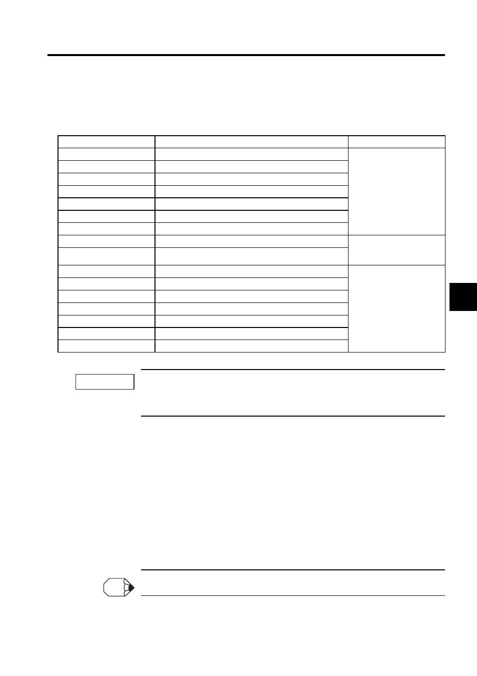
• Examples of Input Signal Allocation
The procedure used to allocate sequence input signals is described using the /S-ON sig-
nal as a typical example.
* Settings 9 through F can be used to reverse signal polarity.
If reverse polarity is set for the Servo-ON, Forward Run Prohibit, or Reverse Run Prohibit signals, safe
operation may not occur when troubles, such as broken signal lines, occur. You must confirm opera-
tional safety if setting reverse polarity is necessary for one or more of these signals.
As shown in the table above, the /S-ON signal can be allocated to any input terminal
from SI0 to SI6. /S-ON is always input when Pn50A.1 is set to 7, and an external signal
line would therefore not be needed.
The /S-ON signal is not used when Pn50A.1 is set to 8. This setting is meaningful only
in the following instances.
• When the factory set input signal are to be replaced by another input signal.
• The signal must be left ON (low level) during normal operation to make the signal
valid when OFF (high level) when forward run prohibit (P-OT) and reverse run pro-
hibit (N-OT) are input. The input terminal signal line must be left ON even in system
configurations that do not require this signal, but unnecessary wiring can be elimi-
nated by setting Pn50A.1 to 8.
Signals are input with OR logic when multiple signals are allocated to the same input circuit.
Pn50A.1 Setting
Description
Remarks
0
Inputs the /S-ON signal from the SI0 (CN1-40) input terminal.
Signal Polarity: Normal
Example:
Servo-ON signal (/S-ON) is
valid when low (ON).
1
Inputs the /S-ON signal from the SI1 (CN1-41) input terminal.
2
Inputs the /S-ON signal from the SI2 (CN1-42) input terminal.
3
Inputs the /S-ON signal from the SI3 (CN1-43) input terminal.
4
Inputs the /S-ON signal from the SI4 (CN1-44) input terminal.
5
Inputs the /S-ON signal from the SI5 (CN1-45) input terminal.
6
Inputs the /S-ON signal from the SI6 (CN1-46) input terminal.
7
Sets /S-ON signal so that it is always valid.
Set the Servo-ON signal (/S-
ON) so that it is always valid
or always invalid.
8
Sets /S-ON signal so that it is always invalid.
9
Inputs the S-ON signal from the SI0 (CN1-40) input terminal.
Signal Polarity: Reversed *
Example:
Servo-ON signal (/S-ON) is
valid when high (OFF).
A
Inputs the S-ON signal from the SI1 (CN1-41) input terminal.
B
Inputs the S-ON signal from the SI2 (CN1-42) input terminal.
C
Inputs the S-ON signal from the SI3 (CN1-43) input terminal.
D
Inputs the S-ON signal from the SI4 (CN1-44) input terminal.
E
Inputs the S-ON signal from the SI5 (CN1-45) input terminal.
F
Inputs the S-ON signal from the SI6 (CN1-46) input terminal.
IMPORTANT
INFO