Yaskawa Large Capacity Sigma II Series User Manual
Page 46
2.3 Connection and Wiring
2-19
2
• Servomotor Terminal Names and Descriptions
The following table shows the name and description of each motor terminal.
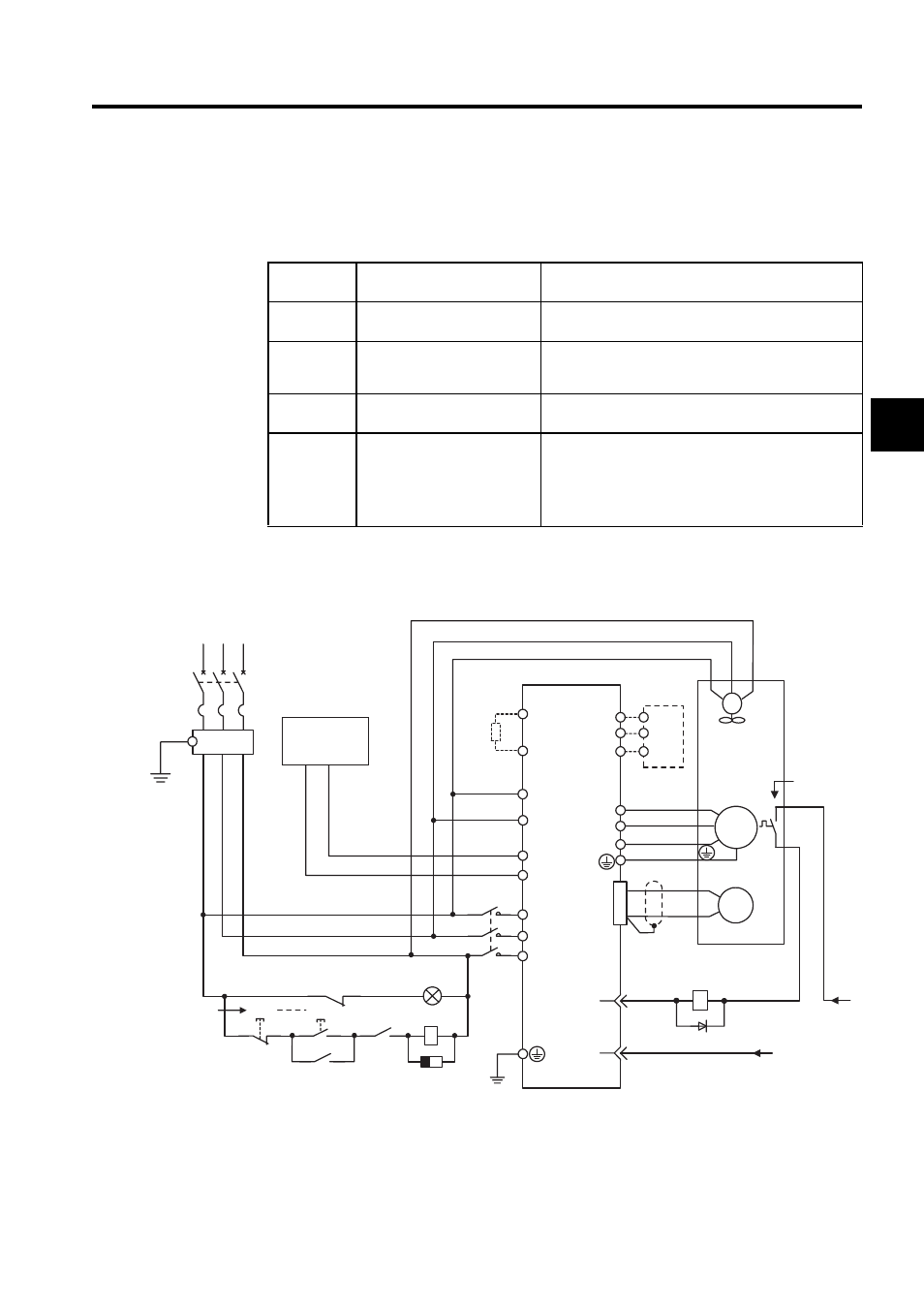
• Typical Wiring Example
Using 400 V, 22 kW or 30 kW
Table 2.2 Servomotor Terminals
Terminal
Symbol
Functions
Description
U, V, W
SERVOPACK connection ter-
minals
Used to connect to the U, V, and W terminals of the
SERVOPACK
U (A), V (B),
W (C)
Fan terminals
Used to connect the fan power supply.
Three-phase 380 to 480 VAC
, 50/60 Hz
A, B
Brake power supply connec-
tion terminals
Used to connect the brake power supply (only when
using servomotors with brakes).
1, 1b
Thermal protector terminals
Used to detect overheating of the servomotor and open
the thermal protector circuit.
Use a sequence that turns OFF the SERVOPACK’s
main circuit power or the servomotor when the thermal
protector circuit opens.
%
+10
- 15
L1/R
DC24P
PG
SERVOPACK
SGDH- DE
U
V
W
M
ALM -
+24V
0 V
24
1Ry
ALM+
31
32
1D
OFF
1MC
1Ry
ON
(Alarm lamp)
1MC
1SUP
1Ry
1MC
L2/S
L3/T
DC24N
B1
B2
Regen-
erative
Resistor
Unit
DU
DV
DW
DB Unit
U(A)
V(B)
W(C)
Fan
1
1b
U
V
W
Main circuit
power
Thermal
protector
FG
FG
CN1
CN2
Three-phase
380 to 480 VAC
(50/60Hz)
+10
-15
%
1MCCB
R
S
T
FIL
1PL
: Lamp for display
: Surge suppressor
: Flywheel diode
1PL
1SUP
1D
1MCCB
FIL
1MC
1Ry
: Circuit breaker (for inverter type)
: Noise filter
: Contactor
: Relay
0V
380 to 480 V
Prepared by customer
Control power
supply
DC24V
+
−