Yaskawa Large Capacity Sigma II Series User Manual
Page 88
4 Parameter Settings and Functions
4.1.3 Limiting Torques
4-12
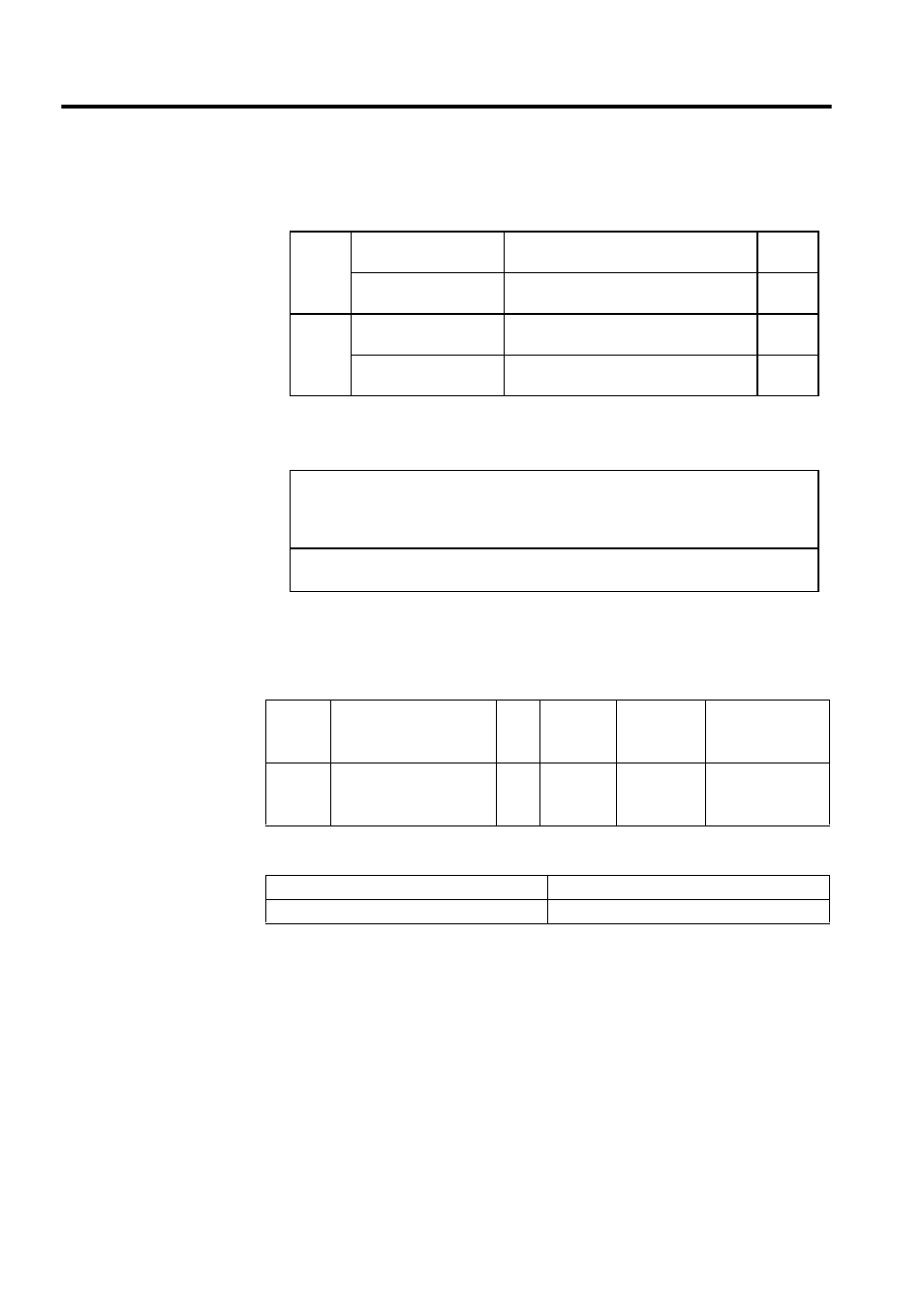
Confirm the allocation of input signals when using this function.(Refer to 4.3.3 Input
Circuit Signal Allocation.) Factory settings are given in the following table.
The following output signals and monitor methods are used when torque is being lim-
ited.
Application Examples:
• Forced stop.
• Robot holding a workpiece.
Set the torque limits when the torque is limited by an external contact input.
See 4.2.10 Torque Limiting by Analog Voltage Reference, Function 1.
/P-CL
CN1-45 at low level
when ON
Use forward torque limit.
Limit:
Pn404
CN1-45 at high level
when OFF
Do not use forward torque limit. Normal
operation.
-
/N-CL
CN1-46 at low level
when ON
Use reverse torque limit.
Limit:
Pn405
CN1-46 at high level
when OFF
Do not use reverse torque limit. Normal
operation.
-
• /CLT
• Monitor Mode
Un005: Nos. 6 and 7 (With factory settings) (Refer to 6.1.7 Operation in Monitor Mode.)
Un006: Depending on output signal allocation conditions.
Condition that outputs a /CLT signal:
Pn50F.0 allocates an output terminal from SO1 to SO3.
Pn404
Forward External Torque
Limit
Unit:
%
Setting
Range:
0 to 800
Factory
Setting:
100
Speed/Torque
Control,
Position Control
Pn405
Reverse External Torque
Limit
Unit:
%
Setting
Range:
0 to 800
Factory
Setting:
100
Speed/Torque
Control,
Position Control
/P-CL (CN1-45) Input
Pn404 torque limit applied.
/N-CL (CN1-46) Input
Pn405 torque limit applied.