Yaskawa Large Capacity Sigma II Series User Manual
Page 20
1 For First-time Users of AC Servos
1.1.2 Technical Terms
1-6
Servo components (1) to (5) are outlined below:
1. Controlled System
In the previous figure, the controlled system is a movable table for which the position or
speed is controlled. The movable table is driven by a ball screw and is connected to the
servomotor via gears. So, the drive system consists of:
• Gears + Ball Screw
This drive system is most commonly used because the power transmission ratio (gear
ratio) can be freely set to ensure high positioning accuracy. However, play in the gears
must be minimized.
The following drive system
1
is also possible when the controlled system is a movable
table:
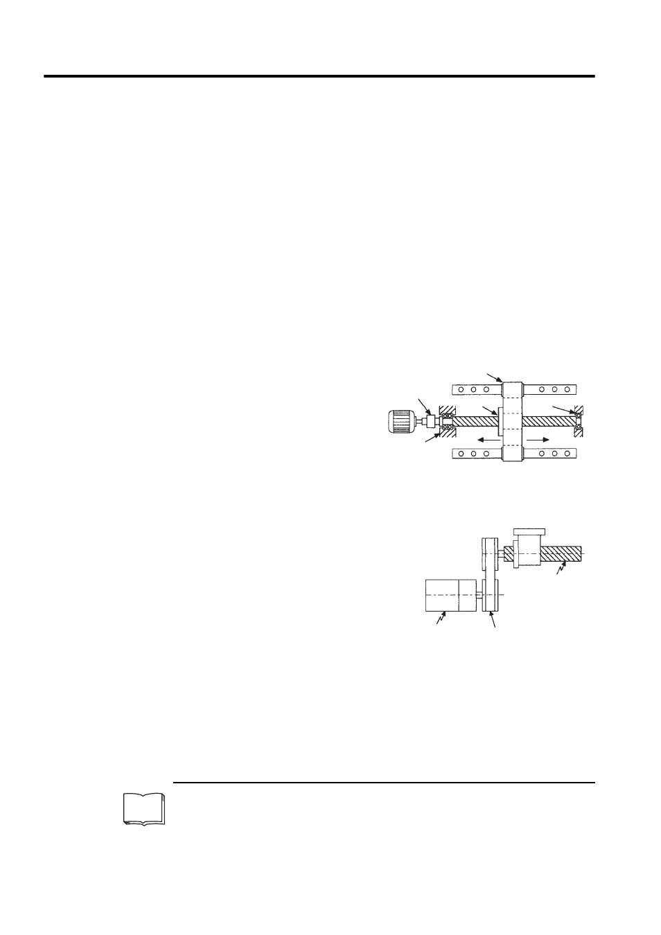
• Coupling + Ball Screw
When the power transmission ratio is
1 : 1, a coupling is useful because it
has no play.
This drive system is widely used for
machining tools.
• Timing Belt + Trapezoidal Screw Thread
A timing belt is a coupling device that allows
the power transmission ratio to be set freely
and that has no play.
A trapezoidal screw thread does not provide
excellent positioning accuracy, so can be
treated as a minor coupling device.
To develop an excellent servo system, it is
important to select a rigid drive system that
has no play.
Configure the controlled system by using an appropriate drive system for the control
purpose.
1
Drive system
Also called a drive mechanism. A drive system connects an actuator (such as a servomotor) to a con-
trolled system and serves a mechanical control component that transmits torque to the controlled sys-
tem, orientates the controlled system, and converts motion from rotation to linear motion and vice
versa.
TERMS
Coupling
Rolling-contact
guide
Ball screw
Rolling-contact
bearing
Housing
Trapezoidal
screw thread
Servomotor
Timing belt