3 using the positioning completed output signal – Yaskawa Large Capacity Sigma II Series User Manual
Page 149
4.5 Forming a Protective Sequence
4-73
4
Note: See 4.3.3 Input Circuit Signal Allocation for other Pn50A.1 settings.
4.5.3 Using the Positioning Completed Output Signal
The basic use and wiring procedure for the positioning completed (/COIN) output signal
(photocoupler output signal) is described below. The signal is output to indicate that servo-
motor operation is completed.
This signal indicates that servomotor movement has been completed during position control.
The host controller uses the signal as an interlock to confirm on the host controller that posi-
tioning is completed.
Pn50A.1 Setting
Description
0
Enables the Servo ON (/S-ON) input signal. (The Servo is OFF when
CN1-40 is open, and is ON when CN1-40 is at 0 V.)
7
Disables the Servo ON (/S-ON) input signal. (The Servo is always ON,
and has the same effect as shorting CN1-40 to 0 V.)
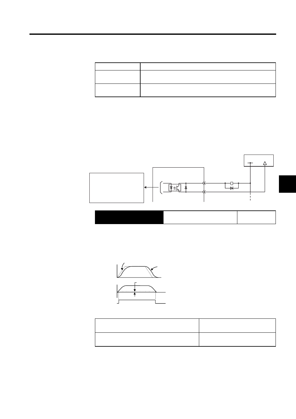
Output
→ /COIN CN1-25
Positioning Completed Output Sig-
nal
Position Control
ON:
Circuit between CN1-25 and 26 is
closed, and CN1-25 is at low level.
Positioning is completed.
(Position error is below the setting.)
OFF:
Circuit between CN1-25 and 26 is open,
and CN1-25 is at high level.
Positioning is not completed.
(Position error is above the setting.)
Setting: Pn500 (positioning completed width)
SERVOPACK
Photocoupler output
(per output)
Maximum operating voltage:
30 VDC
Maximum output current:
50 mA DC
I/O power supply
CN1-25
CN1-26
/COIN+
/COIN-
+24V
0 V
Speed
Reference
Servomotor
/COIN
(CN1-25)
Pn500
Error pulse
(Un008)