6 contact input speed control, Control block diagram – Yaskawa Large Capacity Sigma II Series User Manual
Page 109
4.2 Settings According to Host Controller
4-33
4
Control Block Diagram
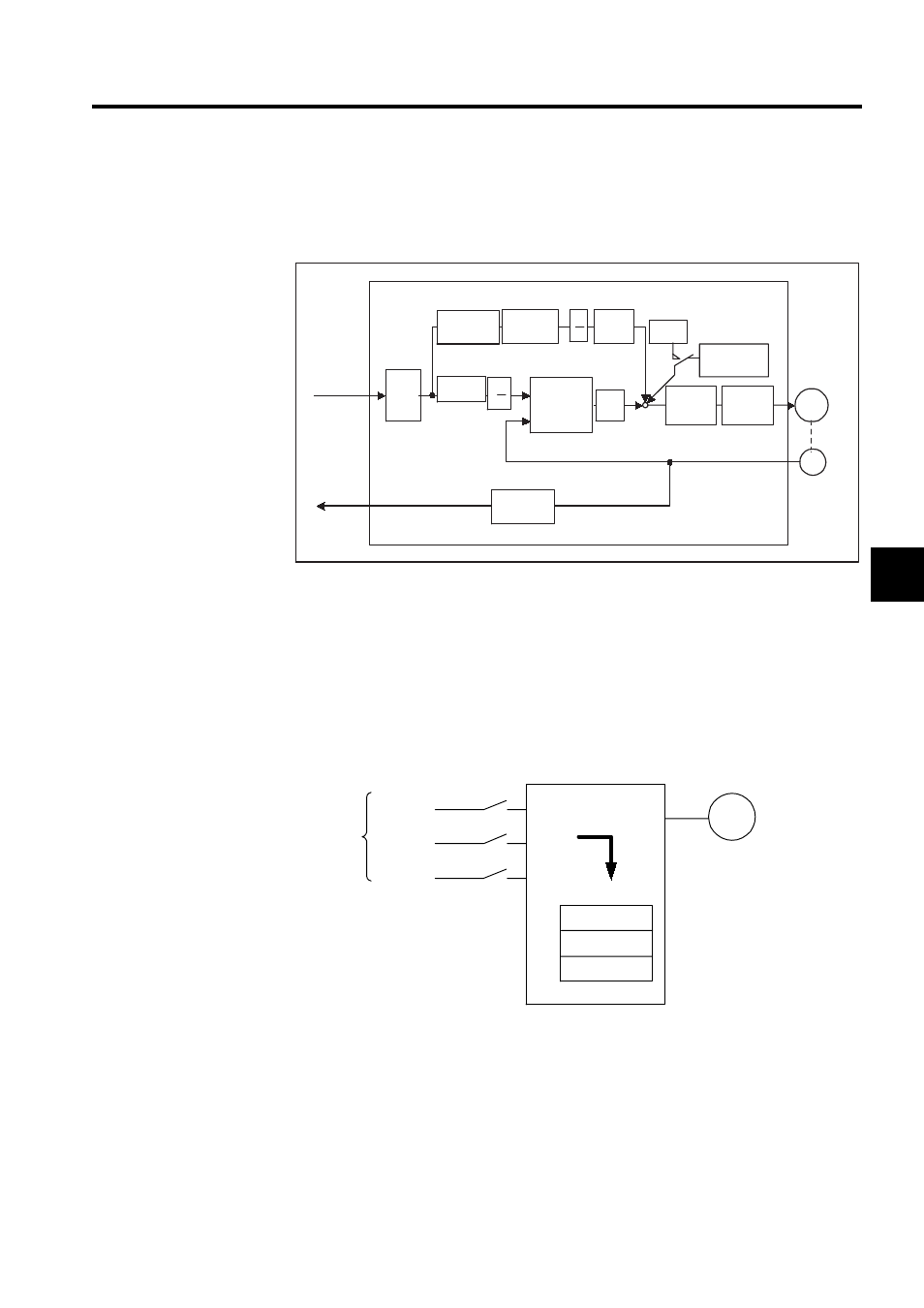
The following diagram illustrates a control block for position control.
4.2.6 Contact Input Speed Control
The contact input speed control function provides easy-to-use speed control. It allows the
user to initially set three different motor speeds with parameters, select one of the speeds
externally by contact input, and operate the servomotor.
Differentiation
Smoothing
X1
X2
X4
Error
counter
Kp
Feed-
forward gain
Primary
lag filter
Bias
Speed
loop
Current
loop
M
Frequency
dividing
Pn201
Pn204
Pn202
Pn203
+
-
Pn102
Pn203
Pn202 Pn10A
Pn107
Pn109
Servomotor
PG
Pn200.0
Reference
pulse
PG signal
output
SERVOPACK (position control)
Encoder
Bias addition
range
Pn108
B
A
B
A
+
+ +
External speed
setting devices and
pulse generators
are not required.
SERVOPACK
CN1-41
CN1-45
CN1-46
Pn301
SPEED 1
Pn302
SPEED 2
Pn303
SPEED 3
Speed selection
The servomotor operates at
the speed set in the parameter.
Servomotor
M
Parameters
Contact
input
/P-CON(/SPD-D)
/P-CL (/SPD-A)
/N-CL (/SPD-B)
- Tag Generator (30 pages)
- MP3300iec (82 pages)
- 1000 Hz High Frequency (18 pages)
- 1000 Series (7 pages)
- PS-A10LB (39 pages)
- iQpump Micro User Manual (300 pages)
- 1000 Series Drive Option - Digital Input (30 pages)
- 1000 Series Drive Option - CANopen (39 pages)
- 1000 Series Drive Option - Analog Monitor (27 pages)
- 1000 Series Drive Option - CANopen Technical Manual (37 pages)
- 1000 Series Drive Option - CC-Link (38 pages)
- 1000 Series Drive Option - CC-Link Technical Manual (36 pages)
- 1000 Series Drive Option - DeviceNet (37 pages)
- 1000 Series Drive Option - DeviceNet Technical Manual (81 pages)
- 1000 Series Drive Option - MECHATROLINK-II (32 pages)
- 1000 Series Drive Option - Digital Output (31 pages)
- 1000 Series Drive Option - MECHATROLINK-II Technical Manual (41 pages)
- 1000 Series Drive Option - Profibus-DP (35 pages)
- AC Drive 1000-Series Option PG-RT3 Motor (36 pages)
- Z1000U HVAC MATRIX Drive Quick Start (378 pages)
- 1000 Series Operator Mounting Kit NEMA Type 4X (20 pages)
- 1000 Series Drive Option - Profibus-DP Technical Manual (44 pages)
- CopyUnitManager (38 pages)
- 1000 Series Option - JVOP-182 Remote LED (58 pages)
- 1000 Series Option - PG-X3 Line Driver (31 pages)
- SI-EN3 Technical Manual (68 pages)
- JVOP-181 (22 pages)
- JVOP-181 USB Copy Unit (2 pages)
- SI-EN3 (54 pages)
- SI-ET3 (49 pages)
- MECHATROLINK-III (35 pages)
- EtherNet/IP (50 pages)
- SI-EM3 (51 pages)
- 1000-Series Option PG-E3 Motor Encoder Feedback (33 pages)
- 1000-Series Option SI-EP3 PROFINET (56 pages)
- PROFINET (62 pages)
- AC Drive 1000-Series Option PG-RT3 Motor (45 pages)
- SI-EP3 PROFINET Technical Manual (53 pages)
- A1000 Drive Option - BACnet MS/TP (48 pages)
- 120 Series I/O Modules (308 pages)
- A1000 12-Pulse (92 pages)
- A1000 Drive Software Technical Manual (16 pages)
- A1000 Quick Start (2 pages)
- JUNMA Series AC SERVOMOTOR (1 page)
- A1000 Option DI-101 120 Vac Digital Input Option (24 pages)