2 settings according to host controller, 1 speed reference – Yaskawa Large Capacity Sigma II Series User Manual
Page 90
4 Parameter Settings and Functions
4.2.1 Speed Reference
4-14
4.2 Settings According to Host Controller
This section describes the procedure for connecting a
Σ
-
ΙΙ Series Servo to a host controller,
including the procedure for setting related parameters.
4.2.1 Speed Reference
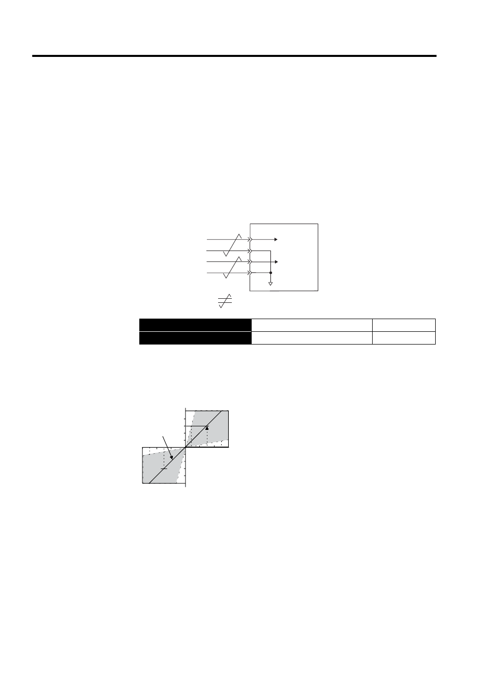
Input the speed reference using the following input signal speed reference input. Since this
signal has various uses, set the optimum reference input for the system created.
The above inputs are used for speed control (analog reference). (Pn000.1 = 0, 4, 7, 9, or A)
Always wire for normal speed control.
The motor speed is controlled in proportion to the input voltage between V-REF and SG.
→ Input V-REF CN1-5
Speed Reference Input
Speed Control
→ Input SG CN1-6
Signal Ground
Speed Control
Torque reference input
(analog voltage input)
Speed reference input
(analog voltage input)
SERVOPACK
Torque
reference
Speed
reference
: represents twisted-pair wires.
CN1-9
CN1-10
CN1-5
CN1-6
T-REF
SG
V-REF
SG
Input voltage (V)
-4
-8
-12
4
8
12
Factory setting
Rated motor speed
Rated motor speed
The slope is set in Pn300.
- Tag Generator (30 pages)
- MP3300iec (82 pages)
- 1000 Hz High Frequency (18 pages)
- 1000 Series (7 pages)
- PS-A10LB (39 pages)
- iQpump Micro User Manual (300 pages)
- 1000 Series Drive Option - Digital Input (30 pages)
- 1000 Series Drive Option - CANopen (39 pages)
- 1000 Series Drive Option - Analog Monitor (27 pages)
- 1000 Series Drive Option - CANopen Technical Manual (37 pages)
- 1000 Series Drive Option - CC-Link (38 pages)
- 1000 Series Drive Option - CC-Link Technical Manual (36 pages)
- 1000 Series Drive Option - DeviceNet (37 pages)
- 1000 Series Drive Option - DeviceNet Technical Manual (81 pages)
- 1000 Series Drive Option - MECHATROLINK-II (32 pages)
- 1000 Series Drive Option - Digital Output (31 pages)
- 1000 Series Drive Option - MECHATROLINK-II Technical Manual (41 pages)
- 1000 Series Drive Option - Profibus-DP (35 pages)
- AC Drive 1000-Series Option PG-RT3 Motor (36 pages)
- Z1000U HVAC MATRIX Drive Quick Start (378 pages)
- 1000 Series Operator Mounting Kit NEMA Type 4X (20 pages)
- 1000 Series Drive Option - Profibus-DP Technical Manual (44 pages)
- CopyUnitManager (38 pages)
- 1000 Series Option - JVOP-182 Remote LED (58 pages)
- 1000 Series Option - PG-X3 Line Driver (31 pages)
- SI-EN3 Technical Manual (68 pages)
- JVOP-181 (22 pages)
- JVOP-181 USB Copy Unit (2 pages)
- SI-EN3 (54 pages)
- SI-ET3 (49 pages)
- MECHATROLINK-III (35 pages)
- EtherNet/IP (50 pages)
- SI-EM3 (51 pages)
- 1000-Series Option PG-E3 Motor Encoder Feedback (33 pages)
- 1000-Series Option SI-EP3 PROFINET (56 pages)
- PROFINET (62 pages)
- AC Drive 1000-Series Option PG-RT3 Motor (45 pages)
- SI-EP3 PROFINET Technical Manual (53 pages)
- A1000 Drive Option - BACnet MS/TP (48 pages)
- 120 Series I/O Modules (308 pages)
- A1000 12-Pulse (92 pages)
- A1000 Drive Software Technical Manual (16 pages)
- A1000 Quick Start (2 pages)
- JUNMA Series AC SERVOMOTOR (1 page)
- A1000 Option DI-101 120 Vac Digital Input Option (24 pages)