3 using more than one servodrive – Yaskawa Large Capacity Sigma II Series User Manual
Page 181
4.8 Special Wiring
4-105
4
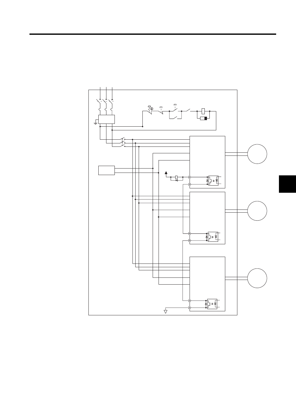
4.8.3 Using More Than One Servodrive
The following diagram is an example of the wiring when more than one Servodrive is used.
Note: Wire the system so that the power supply’s phase S is the ground.
Connect the alarm output (ALM) terminals for the three SERVOPACKs in series to enable
alarm detection relay 1RY to operate.
The output transistor is turned OFF when the ALM output signal invokes the alarm state.
Multiple servos can share a single QF or noise filter. Always select a QF or noise filter that
has enough capacity for the total power capacity (load conditions) of those servos. For
details, refer to 7.5.10 Molded-case Circuit Breaker (MCCB) and 7.5.11 Noise Filter.
Power supply
Power
OFF
Power
ON
Noise filter
SGDH
SERVOPACK
SGDH
SERVOPACK
SGDH
SERVOPACK
SGMBH
servomotor
SGMBH
servomotor
SGMBH
servomotor
R S T
QF
1KM
SUP
1KM
1RY
+24V
L1
L2
L3
DC24P
CN1
31 ALM+
32 ALM -
0V
M
DC24N
L1
L2
L3
DC24P
CN1
31 ALM+
32 ALM -
DC24N
L1
L2
L3
DC24P
CN1
31 ALM+
32 ALM -
DC24N
M
M
1KM
1RY
24 VDC
+
-
- Tag Generator (30 pages)
- MP3300iec (82 pages)
- 1000 Hz High Frequency (18 pages)
- 1000 Series (7 pages)
- PS-A10LB (39 pages)
- iQpump Micro User Manual (300 pages)
- 1000 Series Drive Option - Digital Input (30 pages)
- 1000 Series Drive Option - CANopen (39 pages)
- 1000 Series Drive Option - Analog Monitor (27 pages)
- 1000 Series Drive Option - CANopen Technical Manual (37 pages)
- 1000 Series Drive Option - CC-Link (38 pages)
- 1000 Series Drive Option - CC-Link Technical Manual (36 pages)
- 1000 Series Drive Option - DeviceNet (37 pages)
- 1000 Series Drive Option - DeviceNet Technical Manual (81 pages)
- 1000 Series Drive Option - MECHATROLINK-II (32 pages)
- 1000 Series Drive Option - Digital Output (31 pages)
- 1000 Series Drive Option - MECHATROLINK-II Technical Manual (41 pages)
- 1000 Series Drive Option - Profibus-DP (35 pages)
- AC Drive 1000-Series Option PG-RT3 Motor (36 pages)
- Z1000U HVAC MATRIX Drive Quick Start (378 pages)
- 1000 Series Operator Mounting Kit NEMA Type 4X (20 pages)
- 1000 Series Drive Option - Profibus-DP Technical Manual (44 pages)
- CopyUnitManager (38 pages)
- 1000 Series Option - JVOP-182 Remote LED (58 pages)
- 1000 Series Option - PG-X3 Line Driver (31 pages)
- SI-EN3 Technical Manual (68 pages)
- JVOP-181 USB Copy Unit (2 pages)
- JVOP-181 (22 pages)
- SI-EN3 (54 pages)
- MECHATROLINK-III (35 pages)
- SI-ET3 (49 pages)
- EtherNet/IP (50 pages)
- SI-EM3 (51 pages)
- 1000-Series Option PG-E3 Motor Encoder Feedback (33 pages)
- 1000-Series Option SI-EP3 PROFINET (56 pages)
- PROFINET (62 pages)
- AC Drive 1000-Series Option PG-RT3 Motor (45 pages)
- SI-EP3 PROFINET Technical Manual (53 pages)
- A1000 Drive Option - BACnet MS/TP (48 pages)
- 120 Series I/O Modules (308 pages)
- A1000 12-Pulse (92 pages)
- A1000 Drive Software Technical Manual (16 pages)
- A1000 Quick Start (2 pages)
- JUNMA Series AC SERVOMOTOR (1 page)
- A1000 Option DI-101 120 Vac Digital Input Option (24 pages)