Yaskawa Large Capacity Sigma II Series User Manual
Page 292
7 Servo Selection and Data Sheets
7.3.2 Ratings and Specifications
7-16
* 1. Supply voltage must not exceed the following values. Otherwise, SERVOPACK may mal-
function. If the voltage exceeds these values, use a step-down transformer so that the voltage
will be within the specified range.
SERVOPACK for 400 V: 528 Vrms (max.)
* 2. Use the SERVOPACK within the ambient temperature range. When enclosed in a box, inter-
nal temperatures must not exceed the ambient temperature range.
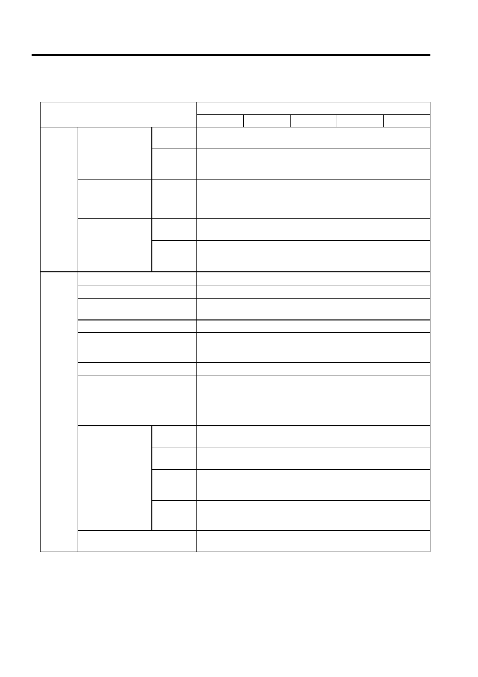
I/O Sig-
nals
Position Output
Form
Phase-A, -B, and -C line driver
Phase-S line driver (only with an absolute encoder)
Frequency
Dividing Ra-
tio
Any
Sequence Input
Signal allo-
cation can
be modified.
Servo ON, P control (or Control Mode switching, forward/reverse motor rota-
tion by internal speed setting, zero clamping, reference pulse prohibited), for-
ward run prohibited (P-OT), reverse run prohibited (N-OT), alarm reset,
forward current limit and reverse current limit (or internal speed selection)
Sequence Output
Fixed Out-
put
Servo alarm, 3-bit alarm codes
Signal allo-
cation can
be modified.
Select three signals among the following: positioning complete (speed agree),
servomotor rotation, servo ready, current limit, speed limit, brake release,
warning, and NEAR signals.
Built-in
Functions
Dynamic Brake (DB)
Operated at main power OFF, servo alarm, servo OFF or overtravel.
Regenerative Processing
Incorporated. External regenerative resistor must be mounted.
Overtravel Prevention (OT)
Dynamic brake stop at P-OT or N-OT, deceleration to a stop, or free run to a
stop
Electronic Gear
0.01
≤ B/A ≤ 100
Protection
Overcurrent, overvoltage, low voltage, overload, regeneration error, main cir-
cuit voltage error, heat sink overheated, no power supply, overflow, overspeed,
encoder error, overrun, CPU error, parameter error, etc.
LED Display
Charge, Power, five 7-segment LEDs (built-in Digital Operator functions)
Analog Monitor (CN5)
Analog monitor connector built in for monitoring speed, torque and other ref-
erence signals.
Speed: 1 V/1000 min
-1
Torque: 1 V/rated torque
Pulses remaining: 0.05 V/1 reference unit or 0.05 V/100 reference units
Communications
Interface
Digital Operator (hand-held model), RS-422A port such as for a personal com-
puter (RS-232C ports under certain conditions)
1:N Com-
munications
Up to N = 14 for RS-422A ports
Axis Ad-
dress Set-
ting
Set with parameters.
Functions
Status display, parameter setting, monitor display, alarm trace-back display,
JOG and auto-tuning operations, speed, torque reference signal and other
drawing functions.
Others
Reverse rotation connection, zero point search, automatic servomotor ID, DC
reactor connection terminal for high power supply frequency control
Table 7.5 SERVOPACK Ratings and Specifications (cont’d)
SERVOPACK Model SGDH-
400 V Series
2BDE
3ZDE
3GDE
4EDE
5EDE