4 output circuit signal allocation – Yaskawa Large Capacity Sigma II Series User Manual
Page 133
4.3 Setting Up the SERVOPACK
4-57
4
* Same as above indicates that the parameter can be set to from 0 to F to allocate input signals to
the following terminals, as shown in the example for the Proportional Control Reference (/P-
CON).
1. Allocation to input terminals SI0 to SI6
2. Setting to always valid or always invalid
3. Allocation to input terminals SI0 to SI6 and receiving the signals at the SERVOPACK with
the reverse logic of the input signal
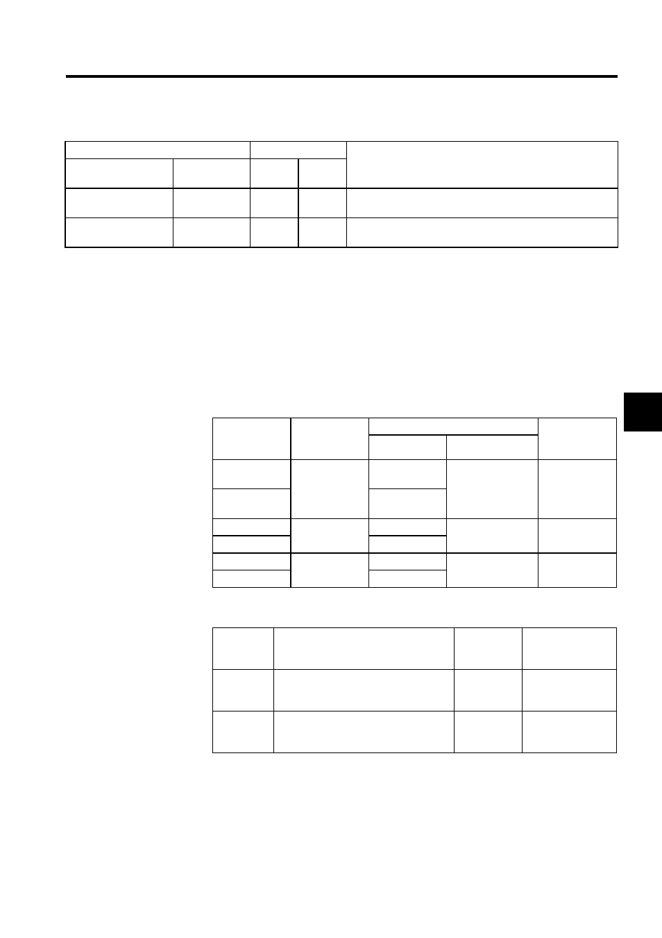
4.3.4 Output Circuit Signal Allocation
Output signal functions can be allocated to the sequence signal output circuits shown below.
The output signal selection parameters and their factory settings are shown below.
Reference Pulse In-
hibit (/INHIBIT)
ON
(low level)
Pn50D.1
0 to F
Same as above. *
Gain Switching
(/G-SEL)
ON
(low level)
Pn50D.2
0 to F
Same as above. *
Table 4.1 Allocation of Other Input Signals (cont’d)
Input Signal
Parameter
Description
Name
Applicable
Logic
Number
Setting
CN1 Connec-
tor Terminal
Numbers
Output
Terminal
Name
Factory Setting
Comments
Symbol
Name
25
SO1
/V-CMP+
(/COIN+)
Speed coincidence
detection (position-
ing completed)
The signal out-
put will vary
depending on the
control mode.
26 (SG)
/V-CMP-
(/COIN-)
27
SO2
/TGON+
Rotation detection
28 (SG)
/TGON-
29
SO3
/S-RDY+
Servo ready
30 (SG)
/S-RDY-
Pn50E
Output Signal Selections 1
Factory
Setting:
3211
Speed/Torque
Control,
Position Control
Pn50F
Output Signal Selections 2
Factory
Setting:
0000
Speed/Torque
Control,
Position Control
Pn510
Output Signal Selections 3
Factory
Setting:
0000
Speed/Torque
Control,
Position Control