Output signal monitor display – Yaskawa Large Capacity Sigma II Series User Manual
Page 238
6 Using the Digital Operator
6.1.7 Operation in Monitor Mode
6-18
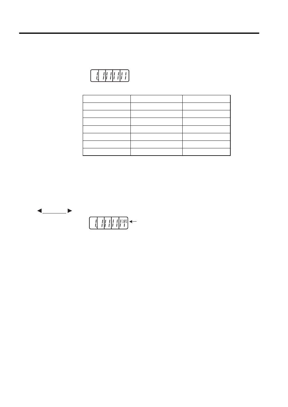
Output Signal Monitor Display
Note: Refer to 4.3.4 Output Circuit Signal Allocation for details on output
terminals.
Output signals are allocated as shown above and displayed on the panel display of the SER-
VOPACK or the Digital Operator. They are indicated by ON/OFF display of seven-segment
LEDs in top and bottom rows. These segments turn ON depending on the output signals
(ON for “L” level and OFF for “H” level).
• When ALM signal operates (alarm at “H”)
LED Number
Output Terminal Name
Factory Setting
1
(CN1-31, -32)
ALM
2
SO1 (CN1-25, -26)
/COIN or /V-CMP
3
SO2 (CN1-27,
-
28)
/TGON
4
SO3 (CN1-29, -30)
/S-RDY
5
(CN1-37)
AL01
6
(CN1-38)
AL02
7
(CN1-39)
AL03
4 3 2 1
Top: OFF ("H" level)
Bottom: ON ("L" level)
Number
7 6 5
EXAMPLE
The top segment of
number 1 is lit.
4 3 2 1
7 6 5
- Tag Generator (30 pages)
- MP3300iec (82 pages)
- 1000 Hz High Frequency (18 pages)
- 1000 Series (7 pages)
- PS-A10LB (39 pages)
- iQpump Micro User Manual (300 pages)
- 1000 Series Drive Option - Digital Input (30 pages)
- 1000 Series Drive Option - CANopen (39 pages)
- 1000 Series Drive Option - Analog Monitor (27 pages)
- 1000 Series Drive Option - CANopen Technical Manual (37 pages)
- 1000 Series Drive Option - CC-Link (38 pages)
- 1000 Series Drive Option - CC-Link Technical Manual (36 pages)
- 1000 Series Drive Option - DeviceNet (37 pages)
- 1000 Series Drive Option - DeviceNet Technical Manual (81 pages)
- 1000 Series Drive Option - MECHATROLINK-II (32 pages)
- 1000 Series Drive Option - Digital Output (31 pages)
- 1000 Series Drive Option - MECHATROLINK-II Technical Manual (41 pages)
- 1000 Series Drive Option - Profibus-DP (35 pages)
- AC Drive 1000-Series Option PG-RT3 Motor (36 pages)
- Z1000U HVAC MATRIX Drive Quick Start (378 pages)
- 1000 Series Operator Mounting Kit NEMA Type 4X (20 pages)
- 1000 Series Drive Option - Profibus-DP Technical Manual (44 pages)
- CopyUnitManager (38 pages)
- 1000 Series Option - JVOP-182 Remote LED (58 pages)
- 1000 Series Option - PG-X3 Line Driver (31 pages)
- SI-EN3 Technical Manual (68 pages)
- JVOP-181 (22 pages)
- JVOP-181 USB Copy Unit (2 pages)
- SI-EN3 (54 pages)
- SI-ET3 (49 pages)
- MECHATROLINK-III (35 pages)
- EtherNet/IP (50 pages)
- SI-EM3 (51 pages)
- 1000-Series Option PG-E3 Motor Encoder Feedback (33 pages)
- 1000-Series Option SI-EP3 PROFINET (56 pages)
- PROFINET (62 pages)
- AC Drive 1000-Series Option PG-RT3 Motor (45 pages)
- SI-EP3 PROFINET Technical Manual (53 pages)
- A1000 Drive Option - BACnet MS/TP (48 pages)
- 120 Series I/O Modules (308 pages)
- A1000 12-Pulse (92 pages)
- A1000 Drive Software Technical Manual (16 pages)
- A1000 Quick Start (2 pages)
- JUNMA Series AC SERVOMOTOR (1 page)
- A1000 Option DI-101 120 Vac Digital Input Option (24 pages)