Yaskawa Large Capacity Sigma II Series User Manual
Page 68
3.1 Two-step Trial Operation
3-5
3
6. Check the input signals.
Check input signal wiring in Monitor Mode using the Digital Operator. See 6.1.7 Oper-
ation in Monitor Mode for more details on the procedure.
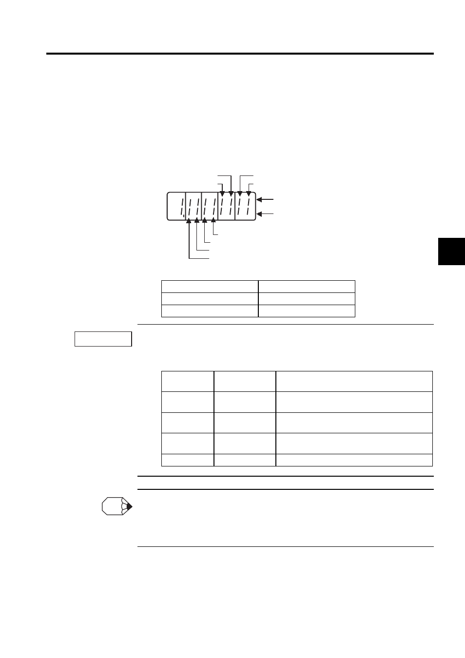
Turn ON and OFF each signal line to see if the LED monitor bit display on the panel
changes as shown below.
The servomotor will not operate properly if the following signal lines are not wired correctly. Short
the signal lines if they will not be used. The input signal selections (parameters Pn50A to Pn50D) can
be used to eliminate the need for external short circuiting.
If an absolute encoder is being used, the servo will not turn ON when the servo ON signal (/S-ON) is
input unless the SEN signal is also ON.
When the SEN signal is checked in monitor mode, the top of the LED will light because the SEN sig-
nal is high when ON.
Input Signal Status
LED Display
OFF (high level)
Top LED indicators light.
ON (low level)
Bottom LED indicators light.
Signal Symbol
Connector Pin
No.
Description
P
-
OT
CN1
-
42
The servomotor can rotate in the forward direction
when this signal line is low (0 V).
N
-
OT
CN1
-
43
The servomotor can rotate in the reverse direction
when this signal line is low (0 V).
/S
-
ON
CN1
-
40
The servomotor is turned ON when this signal line is
low (0 V). Leave the servomotor OFF.
+24VIN
CN1
-
47
Control power supply terminal for sequence signals.
Input signal LED display
/P-CL
/N-CL
Top lights when OFF (high level).
Bottom lights when ON (low level).
/ALM-RST
/P-CON
/S-ON
P-OT
N-OT
SEN
IMPORTANT
INFO