Contents of absolute data, Absolute encoder transmission sequence – Yaskawa Large Capacity Sigma II Series User Manual
Page 167
4.7 Absolute Encoders
4-91
4
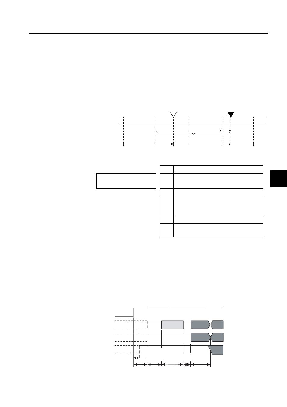
Contents of Absolute Data
• Serial data: Indicates how many turns the motor shaft has made from the reference posi-
tion (position specified at setup).
• Initial incremental pulse: Outputs pulses at the same pulse rate as when the motor shaft
rotates from the origin to the current position at approximately 2500 min
-1
(for 16 bits
when the dividing pulse is at the factory setting)
The final absolute data P
M
can be found by using the following formula.
Absolute Encoder Transmission Sequence
1. Set the SEN signal at high level.
2. After 100 ms, set the system to serial data reception-waiting-state. Clear the incremental
pulse up/down counter to zero.
3. Receive eight bytes of serial data.
4. The system enters a normal incremental operation state approximately 50 ms after the
last serial data is received.
P
E
Current value read by encoder
P
E
= M
× R + P
O
P
M
= P
E
- P
S
M
Multiturn data (rotation count data)
(Use the following for reverse
rotation mode (Pn000.0 = 1).
P
E
= -M
× R + P
O
P
M
= P
E
- R
S
P
O
Number of initial incremental pulses
P
S
Number of initial incremental pulses read at
setup (This is saved and controlled by the host
controller.)
P
M
Current value required for the user’s system.
R
Number of pulses per encoder revolution
(pulse count after dividing, value of Pn201)
Coordinate value
Value M
Reference position (setup)
Current position
-1
0
+1
+2
+3
+3
+2
+1
± 0
P
E
P
M
P
S
P
O
M
× R
SEN signal
PAO
PBO
PSO
Incremental pulses
Incremental pulses
Rotation count serial data
Initial incremental pulses
Undefined
Undefined
Undefined
50 ms
60 ms min.
90ms typ.
260 ms max.
10
ms
max.
Approx. 15ms
1 to 3ms
25msMax
.
Rotation count
serial data
Initial
incremental pulses
(Phase A)
(Phase A)
(Phase B)
(Phase B)