Output signal connections, Important – Yaskawa Large Capacity Sigma II Series User Manual
Page 104
4 Parameter Settings and Functions
4.2.4 Sequence I/O Signals
4-28
The external power supply input terminal is common to sequence input signals.
Contact input signals:
/S
-
ON (CN1-40)
/P
-
CON (CN1
-
41)
P
-
OT (CN1-42)
N
-
OT (CN1-43)
/ALM
-
RST (CN1-44)
/P
-
CL (CN1
-
45)
/N
-
CL (CN1
-
46)
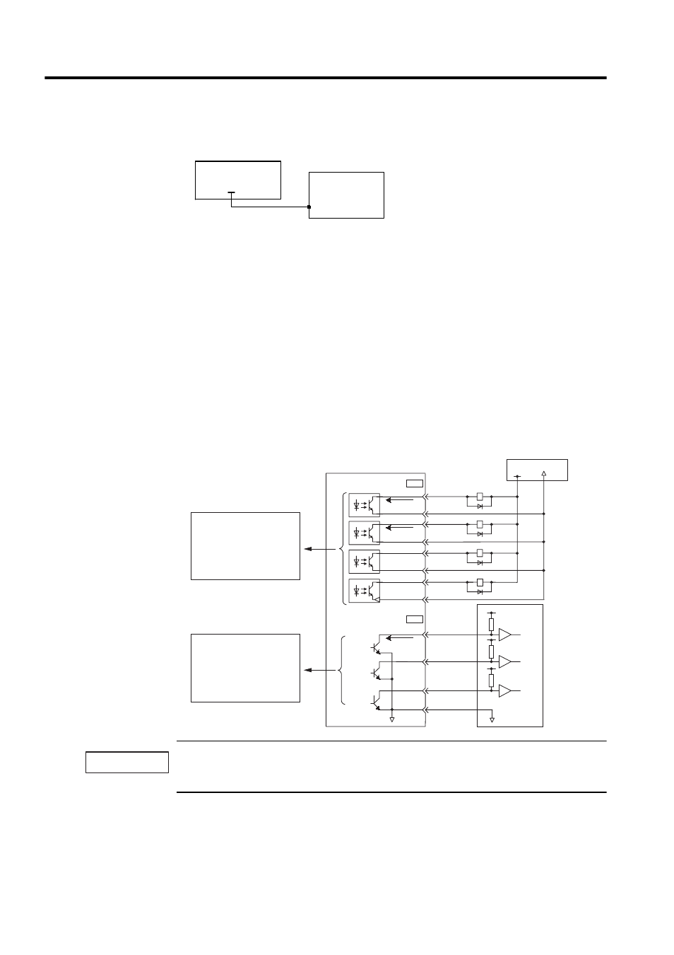
Output Signal Connections
Connect the sequence output signals as shown in the following figure.
Provide an external input power supply; the SERVOPACK does not have an internal 24-V power sup-
ply. Yaskawa recommends using the same type of external power supply as that used for input circuits.
Function allocation for some sequence output signal circuits can be changed.
See 4.3.4 Output Circuit Signal Allocation for more details.
+ 24 V IN
CN1-47
Connect a 24-V external I/O power supply.
I/O power supply
+ 24 V
SERVOPACK
Photocoupler output
per output
Maximum operating
voltage: 30 VDC
Maximum output current:
50 mA DC
Open-collector output
per output
Maximum operating
voltage: 30 VDC
Maximum output current:
20 mA DC
Sequence output signals are
used to indicate SERVOPACK
operating status.
SERVOPACK
Photocoupler
50 mA max.
Host
coutroller
20 mA max.
I/O power supply
0 V
0 V
31
32
25
26
27
28
29
30
ALM+
ALM-
/V-CMP+
/V-CMP-
/TGON+
/TGON-
/S-RDY+
/S-RDY-
37
38
39
1
ALO1
ALO2
ALO3
SG
CN1
+24 V
0 V
CN1
IMPORTANT