Yaskawa Large Capacity Sigma II Series User Manual
Page 305
7.5 Specifications and Dimensional Drawings for Peripheral Devices
7-29
7
Note: 1. Wire sizes were selected for three cables per bundle at 40
°C ambient temperature with the
rated current.
2. Use cable with a minimum withstand voltage of 600 V for main circuits.
3. If cables are bundled in PVC or metal ducts, consider the reduction ratio of the allowable
current.
4. Use heat-resistant cable under high ambient or panel temperatures where normal vinyl
cable will rapidly deteriorate.
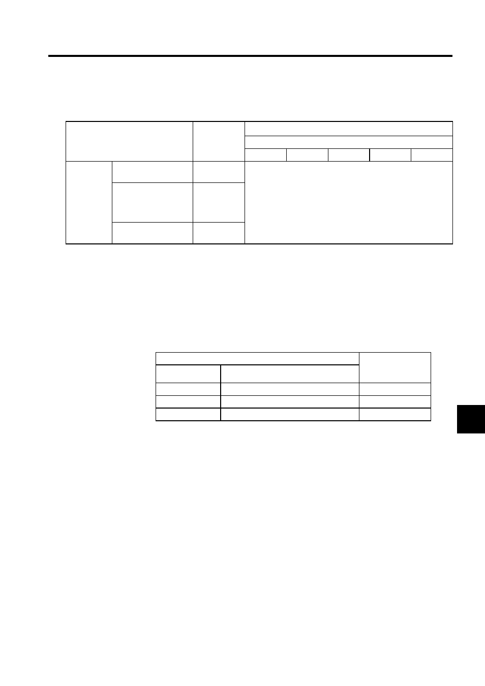
The following table shows types of cables and must be used in conjunction with Table7.6
and Table7.7.
Note: 1. Use cable with a minimum withstand voltage of 600 V for main
circuits.
2. If cables are bundled in PVC or metal ducts, consider the reduction
ratio of the allowable current.
3. Use heat-resistant cable under high ambient or panel temperatures
where normal vinyl cable will rapidly deteriorate.
Table 7.7 Servomotor Wire Sizes
External Terminal Name
Terminal
Symbol
Wire Size Examples [mm
2
(in
2
)]
SERVOPACK Model SGDH-
2BDE
3ZDE
3GDE
4EDE
5EDE
Offline Ter-
minals
Fan Terminals
U (A), V (B),
W (C)
HIV 1.25 (0.002) min.
Brake Power Supply
Connection Terminals
(for servomotor with
brake only)
A, B
Thermal Protector Ter-
minals
1, 1b
Cable Types
Allowable
Conductor
Temperature
°C
Symbol
Name
PVC
Normal vinyl cable
-
IV
600-V vinyl cable
60
HIV
Temperature-resistant vinyl cable
75