Using contact input speed control – Yaskawa Large Capacity Sigma II Series User Manual
Page 110

4 Parameter Settings and Functions
4.2.6 Contact Input Speed Control
4-34
Using Contact Input Speed Control
Follow steps 1 to 3 below to use the contact input speed control function.
1. Set contact input speed control as shown below.
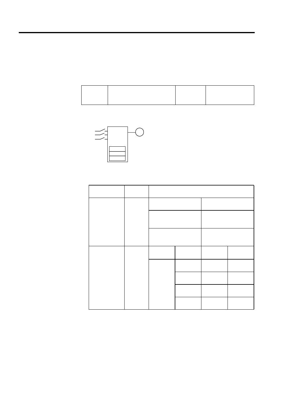
The speed can be controlled via contact inputs.
Meanings for the following signals change when the contact input speed control func-
tion is used.
Note: 1. 0: OFF (high level); 1: ON (low level)
2. /P-CON, /P-CL and /N-CL functions change as shown in the table
above when Pn000.1 is set to 3, 4, 5, or 6. The function is switched
automatically when Pn50A. 0 is set to 0.
3. The /SPD-D, /SPD-A, and /SPD-B signals can be used only when
signals are allocated to the input circuits. See 4.3.3 Input Circuit
Signal Allocation.
Pn000.1
Control Mode Selection
Factory
Setting:
0
Speed/Torque Control,
Position Control
Pn000.1 Setting
Descrip-
tion
Input Signal
0, 1, 2, 7, 8, 9,
A, B
Contact
input speed
control
function
not used.
/P-CON (CN1-41)
Used to switch between P
and PI control.
/P-CL (CN1-45)
Used to switch between for-
ward external torque limit
ON and OFF.
/N-CL (CN1-46)
Used to switch between
reverse external torque limit
ON and OFF.
3, 4, 5, 6
Contact
input speed
control
function
used.
/P-CON
(/SPD-D)
/P-CL
(/SPD-A)
/N-CL
(/SPD-B)
Speed
Setting
Direction of
rotation
0: Forward
1: Reverse
0
0
0 reference,
etc.
0
1
SPEED1
(Pn301)
1
1
SPEED2
(Pn302)
1
0
SPEED3
(Pn303)
SERVOPACK
SPEED 1
SPEED 2
SPEED 3
Servomotor
Contact
input
Servo operates
at the internally
set speed.
M
