Selecting a thermal relay – Yaskawa Large Capacity Sigma II Series User Manual
Page 334
7 Servo Selection and Data Sheets
7.5.15 Thermal Relays
7-58
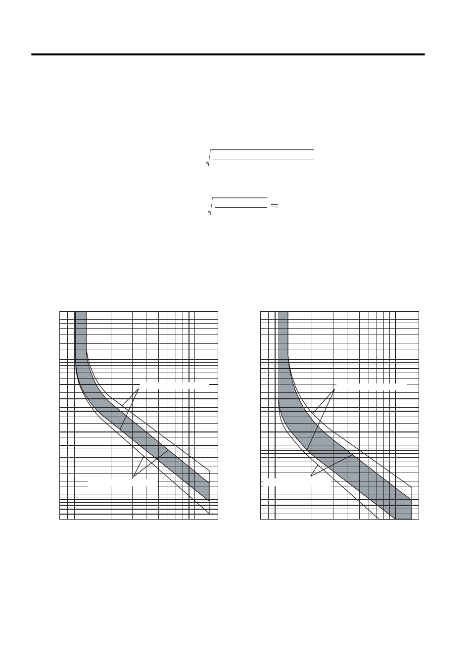
Selecting a Thermal Relay
When preparing the dynamic brake resistor and regenerative resistor separately, select a
thermal relay by calculating the setting current of the thermal relay according to the value
and capacity of the resistor being used, as shown in the following equation.
Example for a JUSP-RA08
Select a thermal relay that has operating characteristics equivalent to those of the recom-
mended product.
Refer to the following diagrams for the operating characteristics of the recommended ther-
mal relays.
Setting current =
Resistance capacity (W)
× 0.2
Resistance value (
Ω)
Setting current =
2000 (W)
× 0.2
2.4 (
Ω)
14 A
Cold Start Characteristics (Ambient Temperature of 20
°C)
Hot Start Characteristics (Ambient Temperature of 20
°C)
60
50
40
30
10
8
6
5
4
3
2
60
50
40
30
20
10
8
6
5
4
3
2
1
0.8
0.6
0.5
0.4
0.3
20
Multiplier of setting current
Multiplier of setting current
xln [A]
xln [A]
60
50
40
30
10
8
6
5
4
3
2
60
50
40
30
20
10
8
6
5
4
3
2
1
0.8
0.6
0.5
0.4
0.3
20
Operating time
Operating time
2
1
3
4
5 6 7 8 9 10
15
2
1
3
4
5 6 7 8 9 10
15
Minutes
Seconds
Minutes
Seconds
Rated at 18 to 26 A min.
Rated at 12 to 18 A min.
Rated at 18 to 26 A min.
Rated at 12 to 18 A min.