Setting level 2: external torque limit – Yaskawa Large Capacity Sigma II Series User Manual
Page 87
4.1 Settings According to Device Characteristics
4-11
4
Use the following table to select which terminal will output the /CLT signal.
Note: Multiple signals allocated to the same output circuit are output using
OR logic. Set other output signals to a value other than that allocated
to the /CLT signal in order to output the /CLT signal alone. See 4.3.4
Output Circuit Signal Allocation.
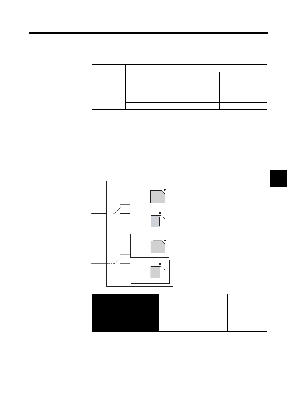
Setting Level 2: External Torque Limit
A contact input signal is used to enable the torque (current) limits previously set in parame-
ters. Torque limits can be set separately for forward and reverse rotation.
This is the external torque (current) limit input for forward and reverse rotation.
Parameter
Setting
Output Terminal (CN1-)
∗
1
∗
2
Pn50F.0
0
-
-
1
25
26
2
27
28
3
29
30
→ Input /P-CL CN1-45
Forward External Torque Limit In-
put
Speed/Torque
Control,
Position Control
→ Input /N-CL CN1-46
Reverse External Torque Limit In-
put
Speed/Torque
Control,
Position Control
/P-CL
CN1-45
/N-CL
CN1-46
Torque
Torque
Torque
Torque
SERVOPACK
Forward
rotatioin
Rotation
speed
Rotation
speed
Rotation
speed
Rotation
speed
Reverse
rotation
Torque limit
Pn402 or Pn404
(limited by whichever
is smaller)
Torque limit
Pn403 or Pn405
(limited by whichever
is smaller)
Torque limit
Pn402
Torque limit
Pn403