1 interface circuit, Sen signals, Important – Yaskawa Large Capacity Sigma II Series User Manual
Page 161
4.7 Absolute Encoders
4-85
4
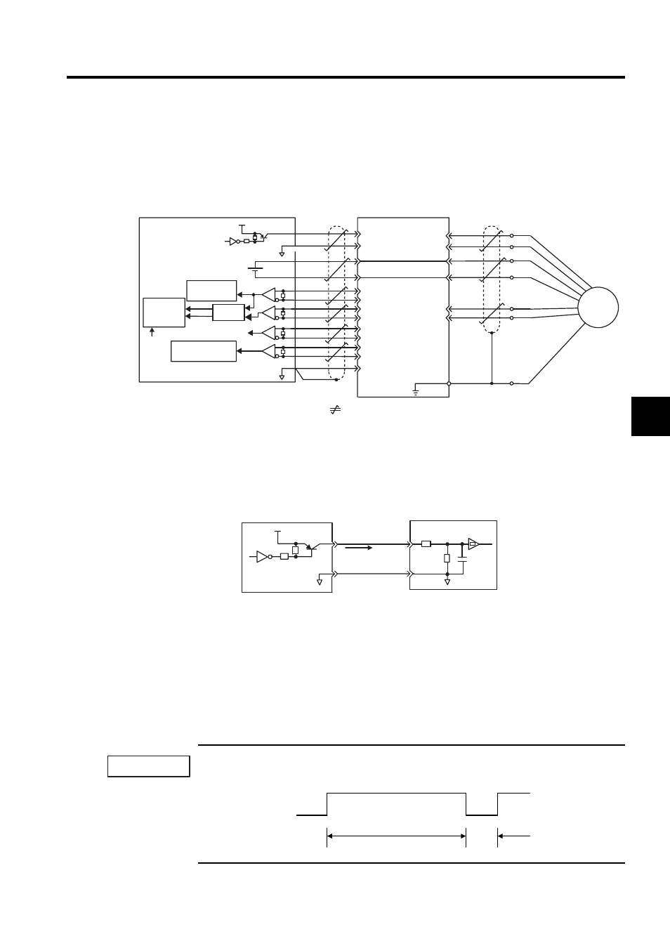
4.7.1 Interface Circuit
The following diagram shows the standard connections for an absolute encoder mounted to a
servomotor.
Applicable line drivers: SN75175 or KM3486 by T/I.
Terminating resistance R: 220 to 470
Ω
SEN Signals
• Let at least three seconds elapse after turning ON the power before raising the SEN sig-
nal to high level.
• When the SEN signal is changed from low level to high level, the multiturn data and ini-
tial incremental pulses are output.
• Until these operations are completed, the motor cannot be operated regardless of the sta-
tus of the servo ON signal (/S-ON).
If for some reason it is necessary to turn OFF a SEN signal that is already ON, and then to turn it back
ON again, maintain the high level for at least 1.3 seconds before turning it ON and OFF.
Host controller
SERVOPACK
Battery
Serial interface
circuit
Edge
detection
Line driver
Up/down
counter
Serial interface
circuit
Clear
Shielded wire (shell)
: represents twisted-pair wires.
Connector shell
R
PG5V
PG0V
BAT(+)
PS
/PS
BAT(- )
PSO
BATO
/PSO
PCO
/PCO
PBO
/PBO
PAO
/PAO
BAT
SEN
OSEN
SG
R
R
R
PA
PB
PC
PS
+5V
7406
0V
+
-
0V
4
2
21
22
33
34
35
36
19
48
49
1
20
CN1
1
2
3
4
5
6
CN2
H (1)
G (2)
T (3)
S (4)
C (5)
D (6)
J
PG
UP
DOWN
4.7k
Ω
SEN
CN1-4
OSEN
Host controller
SERVOPACK
CN1-2
+5V
Approx. 1 mA
at high level
0V
7406 or
equivalent
100
Ω
0V
1
µF
PNP is recommended for transistors.
Signal Levels
High level: 4.0 V min.; Low level: 0.8 V max.
IMPORTANT
OFF
ON = high level
1.3 s min.
OFF
ON
15 ms
min.
SEN signal