Peripheral device types and capacities – Yaskawa Large Capacity Sigma II Series User Manual
Page 306

7 Servo Selection and Data Sheets
7.5.1 Cable Specifications and Peripheral Devices
7-30
Peripheral Device Types and Capacities
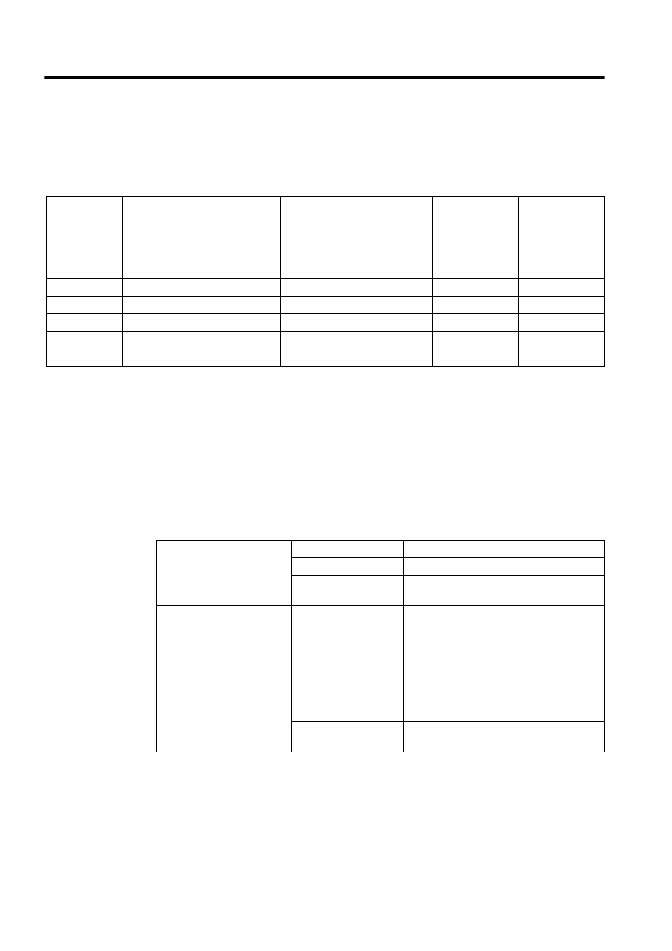
Table7.8 shows SERVOPACK peripheral device types and capacities.
* 1. Braking characteristics at 25
°C: 200% for 2 s min., 700% for 0.01 s min.
* 2. Manufactured by SCHAFFNER. (Available from Yaskawa Controls Co., Ltd.)
* 3. Manufactured by Yaskawa Controls Co., Ltd.
* 4. The supply voltage capacity shown is the value for a rated load.
Table7.9 shows appropriate cables for CN1 and CN2 SERVOPACK connectors.
Wire sizes were selected for three cables per bundle at 40
°
C ambient temperature with the
rated current.
Table 7.8 Peripheral Device Types and Capacities
SERVOPACK
Model
SGDH-
Applicable Servo-
motor Model
SGMBH-
Power Sup-
ply Capac-
ity
*4
kVA
Molded-case
Circuit Breaker
(MCCB) or
Fuse
Capacity
*1
A
Main Power
Inrush Current
(peak value)
A
Recommended
Line Filter
*2
Magnetic Con-
tactor
*3
2BDE
2BDA
36.7
100
162
FN258L-75-34
HI-65J (65 A)
3ZDE
3ZDA
50.1
150
650
FN258L-100-35
HI-80J (80 A)
3GDE
3GDA
61.8
150
650
FN258L-130-35
HI-80J (80 A)
4EDE
4EDA
75.2
225
1300
FN258L-180-07
HI-125J (125 A)
5EDE
5EDA
91.9
225
1300
FN258L-180-07
HI-125J (125 A)
Table 7.9 Cables for CN1 and CN2 Connectors
Control I/O Signal
Connector
CN1
Cable
Use twisted-pair or shielded twisted-pair wire.
Applicable wire
AWG24, 26, 28, 30
Finished cable dimen-
sion
φ16.0 mm (0.63 in) max.
PG Signal
Connector
CN2
Cable
Use Yaskawa cable, or shielded twisted-pair
wire if Yaskawa cable is not used.
Applicable wire
AWG24, 26, 28, 30
Use AWG22 (0.33 mm
2
(0.001 in
2
)) for the
encoder power supply and FG line, and
AWG26 (0.12 mm
2
(0.0002 in
2
)) for other sig-
nals. These conditions permit wiring distances
up to 20 m (65.6 ft).
Finished cable dimen-
sion
φ6.8 mm (0.27 in) max.
