4 using the holding brake, Wiring example, Important – Yaskawa Large Capacity Sigma II Series User Manual
Page 142
4 Parameter Settings and Functions
4.4.4 Using the Holding Brake
4-66
4.4.4 Using the Holding Brake
The holding brake is used when a servodrive controls a vertical axis. In other words, a servo-
motor with brake prevents the movable part from shifting due to gravity when system power
goes OFF.
The brake built into the SGMBH servomotor with brakes is a de-energization brake, which is used only
to hold and cannot be used for braking. Use the holding brake only to hold a stopped motor. Brake
torque is at least 120% of the rated motor torque.
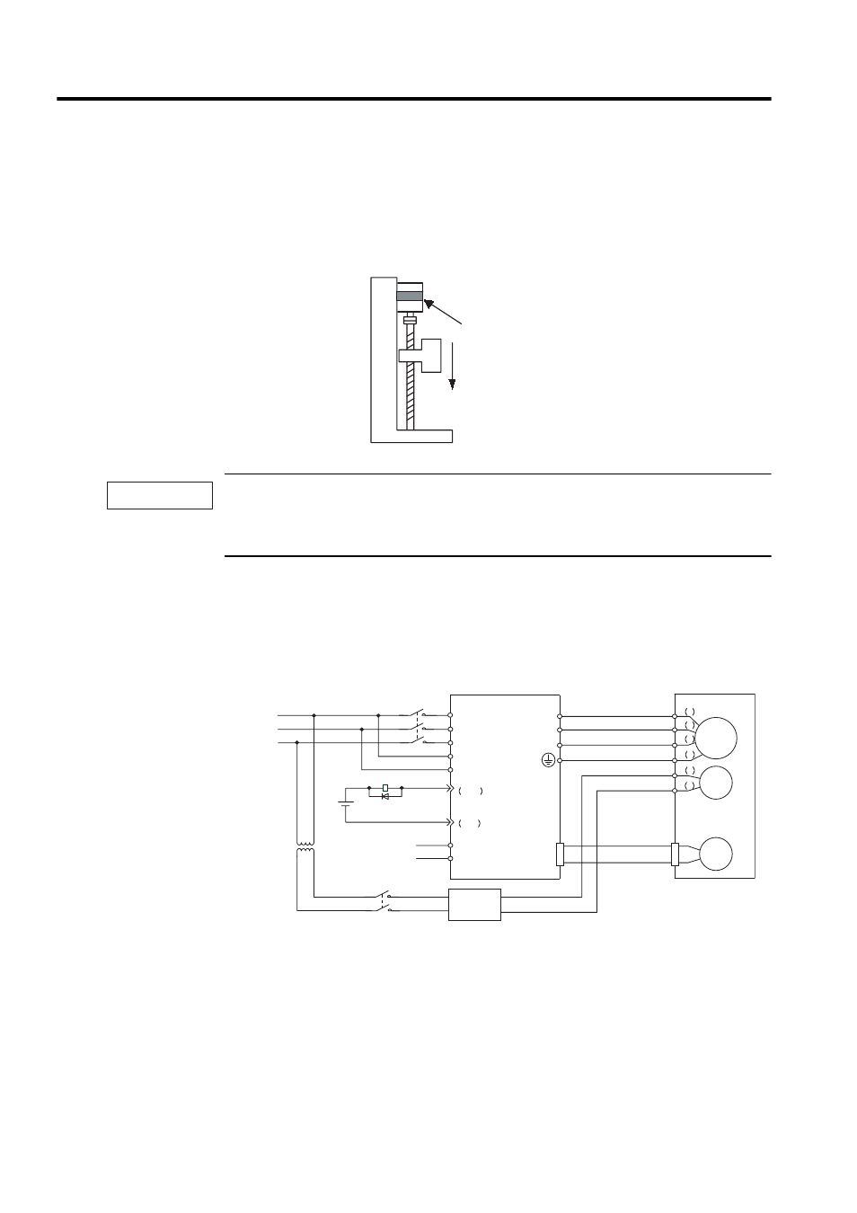
Wiring Example
Use the SERVOPACK contact output signal /BK and the brake power supply to form a brake
ON/OFF circuit. The following diagram shows a standard wiring example.
*1 and *2 are the output terminals allocated with Pn50F.2.
Servomotor
Prevents the movable part from
shifting due to gravity when
system power goes OFF.
Holding brake
IMPORTANT
A 1
B 2
C 3
D 4
E 5
F 6
V
U
W
CN2
BK-R
BK-R Y
BK-RY
+24 V
L1
L2
L3
380 to 480 V
0V
/BK-
/BK+
CN1-
∗1
CN2 -
∗2
Servomotor
with brake
SERVOPACK
Power supply
transformer
(400 V / 200 V)
Power supply
Three-phase 380 to 480 VAC
Red
Black
Blue or
yellow
White
BK-RY: Brake control relay
Brake power supply
Brake power supplies are available in
200-V and 100-V models.
AC
DC
M
BK
PG
DC24P
DC24V
+
-
DC24N