Sequence input circuit interface, Output circuit interfaces – Yaskawa Large Capacity Sigma II Series User Manual
Page 55
2 Basic Operation
2.4.4 Interface Circuits
2-28
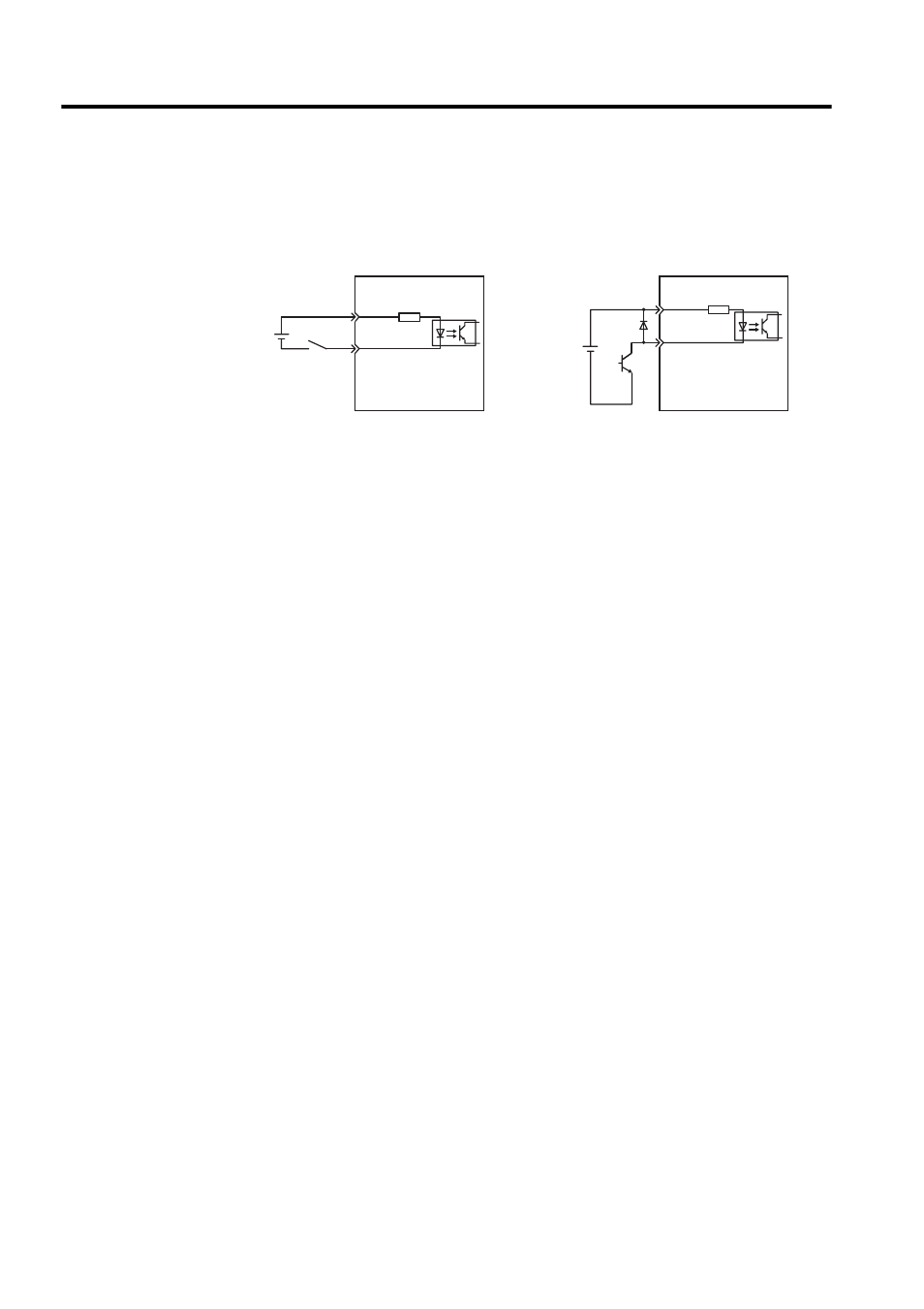
Sequence Input Circuit Interface
The sequence input circuit interface connects through a relay or open-collector transistor cir-
cuit. Select a low-current relay otherwise a faulty contact will result.
Output Circuit Interfaces
Any of the following three types of SERVOPACK output circuits can be used. Form an input
circuit at the host controller that matches one of these types.
• Connecting to a Line-driver Output Circuit
Encoder serial data converted to two-phase (phase A and B) pulse output signals (PAO,
/PAO, PBO, /PBO), origin pulse signals (PCO, /PCO) and phase-S rotation signals
(PSO, /PSO) are output via line-driver output circuits that normally comprise the posi-
tion control system at the host controller. Connect the line-driver output circuit through
a line receiver circuit at the host controller.
See 2.5 Wiring Encoders for connection circuit examples.
• Connecting to an Open-collector Output Circuit
Alarm code signals are output from open-collector transistor output circuits.
Connect an open-collector output circuit through a photocoupler, relay or line receiver
circuit.
3.3 k
Ω
+24VIN
+24VIN
3.3 k
Ω
/S-ON, etc.
Servoamp
24 VDC
50 mA min.
/S-ON, etc.
Servoamp
24 VDC
50 mA min.