5 control mode selection – Yaskawa Large Capacity Sigma II Series User Manual
Page 135
4.3 Setting Up the SERVOPACK
4-59
4
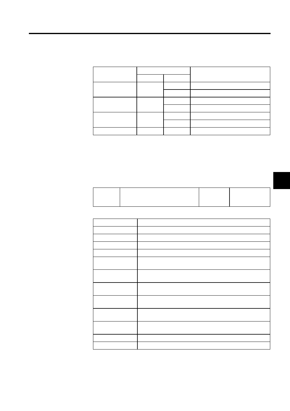
The settings specify which of the connector CN1 output signals are to be reversed.
4.3.5 Control Mode Selection
The SGDH SERVOPACK offers speed control, position control, torque control, and the
other control modes shown in the following table.
The following parameter is used to set the control mode.
Output Signal
Parameter
Meaning
Number
Setting
SO1 (CN1-25, 26)
Pn512.0
0
Output signal not reversed.
1
Output signal reversed.
SO2 (CN1-27, 28)
Pn512.1
0
Output signal not reversed.
1
Output signal reversed.
SO3 (CN1-29, 30)
Pn512.2
0
Output signal not reversed.
1
Output signal reversed.
Not used.
Pn512.3
-
-
Pn000.1
Control Mode Selection
Factory
Setting:
0
Speed/Torque
Control,
Position Control
Pn000.1 Setting
Control Mode
0
Speed Control (Analog Reference)
1
Position Control (Pulse Train Reference)
2
Torque Control (Analog Reference)
3
Contact Input Speed Control Selection (Contact Reference)
4
Contact Input Speed Control Selection (Contact Reference)
↔ Speed Control (Analog Reference)
5
Contact Input Speed Control Selection (Contact Reference)
↔ Position Control (Pulse Train Reference)
6
Contact Input Speed Control Selection (Contact Reference)
↔ Torque Control (Analog Reference)
7
Position Control (Pulse Train Reference)
↔ Speed Control (Analog Reference)
8
Position Control (Pulse Train Reference)
↔Torque Control (Analog Reference)
9
Torque Control (Analog Reference)
↔ Speed Control (Analog Reference)
A
Speed Control (Analog Reference)
↔ Zero Clamp Control
B
Position Control (Pulse Train Reference)
↔ Position Control (Inhibit)