Yaskawa Large Capacity Sigma II Series User Manual
Page 155
4.5 Forming a Protective Sequence
4-79
4
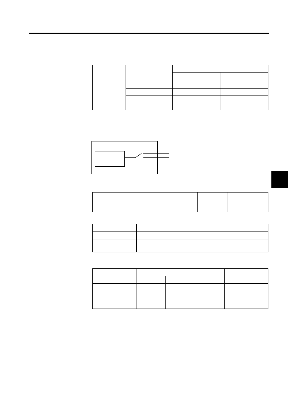
Pn50F.3 is used to allocate the /WARN output signals above.
Note: Multiple signals allocated to the same output circuit are output using
OR logic. Set other output signals to a value other than that allocated
to the /WARN signal in order to use the /WARN output signal alone.
See 4.3.4 Output Circuit Signal Allocation.
The following parameter is used to output warning details with an alarm code.
The following warning codes are output in 3 bits.
Parameter
Setting
Output Terminal (CN1-)
∗
1
∗
2
Pn50F.3
0
-
-
1
25
26
2
27
28
3
29
30
Pn001.3
Warning Code Output Selection
Factory
Setting:
0
Speed/Torque
Control,
Position Control
Pn001.3 Setting
Description
0
Outputs alarm codes alone for alarm codes ALO1, ALO2 and ALO3.
1
Outputs both alarm and warning codes for alarm codes ALO1, ALO2 and
ALO3. Outputs an alarm code when an alarm occurs.
Warning Indication
Warning Code Output
Warning Description
ALO1
ALO2
ALO3
A.91
ON signal
(low level)
OFF signal
(high level)
OFF signal
(high level)
Overload
A.92
OFF signal
(high level)
ON signal
(low level)
OFF signal
(high level)
Regenerative overload
/WARN
Warning output
signal
Pn50F.3
1
2
3
CN1-25,26 (SO1)
CN1-27,28 (SO2)
CN1-29,30 (SO3)
Output terminals