Instrument connection examples – Yaskawa Large Capacity Sigma II Series User Manual
Page 382
8.2 Troubleshooting
8-43
8
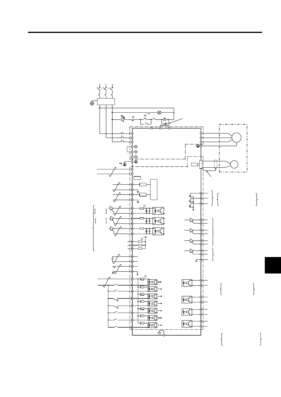
Instrument Connection Examples
The following diagram shows a connection example of reference and control I/O.
3
2
18
13
15
12
7
8
10
6
1RY
V -REF
T-REF
SG
SG
*2.
CN1
PULS
SIGN
Open-collector
reference
power supply
CLR
/PULS
SIGN
/SIGN
CLR
/CLR
+
-
+5V
0V
SEN
SG
PL1
PL2
PL3
1k
+12 V
PULS
150
BAT(+)
BAT(-)
ALO1
ALO2
ALO3
PBO
PCO
/PBO
PAO
/PAO
/PCO
/PSO
PSO
SG
*4.
/V-CMP+
(/COIN+)
/V-CMP-
(/COIN-)
/TGON+
/TGON-
/S-RDY+
ALM+
ALM-
L1
L2
U
V
W
A(1)
B(2)
C(3)
D(4)
B1
B2
*1.
FG
A/D
4
22
21
11
14
9
5
27
28
29
30
31
32
25
26
48
19
33
34
35
36
20
49
1
37
38
39
+24V
+24V
3.3k
1Ry
2Ry
N-LS
P-LS
3Ry
6Ry
7Ry
/S-ON
/P-CON
N-OT
P-OT
/ALM-
RST
/P-CL
47
41
43
42
44
45
/N-CL
46
40
1KM
*2.
/S-RDY-
1KM
PL
1RY
1KM
QF1
L3
B3
*5.
*6.
24V
0V
1
2
+24V
*7.
Three-phase 380 to 480 VAC
(50/60 Hz)
+10%
- 15%
Power
OFF
Power
ON
Be sure to attach a surge suppressor to the excitation
coil of the magnetic contactor and relay.
SGDH
SERVOPACK
Optical
encoder
Servomotor
Be sure to prepare the end of
the shielded wire properly.
Be sure to
ground.
Reference speed
±2 to ±10 V/rated motor speed
Torque reference
±1 to ±10 V/rated motor torque
Control power
Alarm code output
Maximum operating voltage:
30 VDC
Maximum operating current:
20 mA DC
Photocoupler output
Maximum operating voltage:
30 VDC
Maximum operating current:
50 mA DC
PG dividing ratio output
Applicable line receiver
SN75175 or MC3486 manufac-
tured by T/I or the equivalent
Amount of phase-S rotation
Serial data output
Applicable line receiver
SN75175 or MC3486
manufactured by T/I or the
equivalent
Positioning completed
(ON when positioning is
completed)
Position
reference
CW
phase A
phase B
CCW
Backup battery 2.8 to 4.5 V
*3.
Servo ON with 1Ry ON
Reverse run prohibited with
N-LS OPEN
Forward run prohibited with
P-LS OPEN
Alarm reset with 3Ry ON
Forward current limit ON with 6Ry ON
Reverse current limit ON with 7Ry ON
Connect shield to connector shell.
Connector shell
Servo ON
Proportional control
(P control)
Reverse run
prohibited
Forward run
prohibited
Alarm reset
Reverse current
limit ON
Forward current
limit ON
SEN signal input *3.
P control with 2Ry ON
Speed coincidence detection
(ON when speed coincides)
Servo ready output
(ON when ready)
Servo alarm output
(OFF with an alarm)
TGON output
(ON at levels above the setting)
Noise filter
CN2
LPF
LPF
PG
M