2 mechanical characteristics, Allowable radial and thrust loads, Mechanical tolerance – Yaskawa Large Capacity Sigma II Series User Manual
Page 287
7.2 Servomotor Ratings and Specifications
7-11
7
7.2.2 Mechanical Characteristics
The following sections provide the mechanical characteristics of the SGMBH servomotors.
Allowable Radial and Thrust Loads
The following table shows the allowable loads on the output shafts of the SGMBH servomo-
tors.
Conduct mechanical design such that the radial loads and thrust loads do not exceed the val-
ues shown in Table7.3.
Note: Allowable radial and thrust loads shown above are the maximum val-
ues that could be applied to the shaft end from motor torque or other
loads.
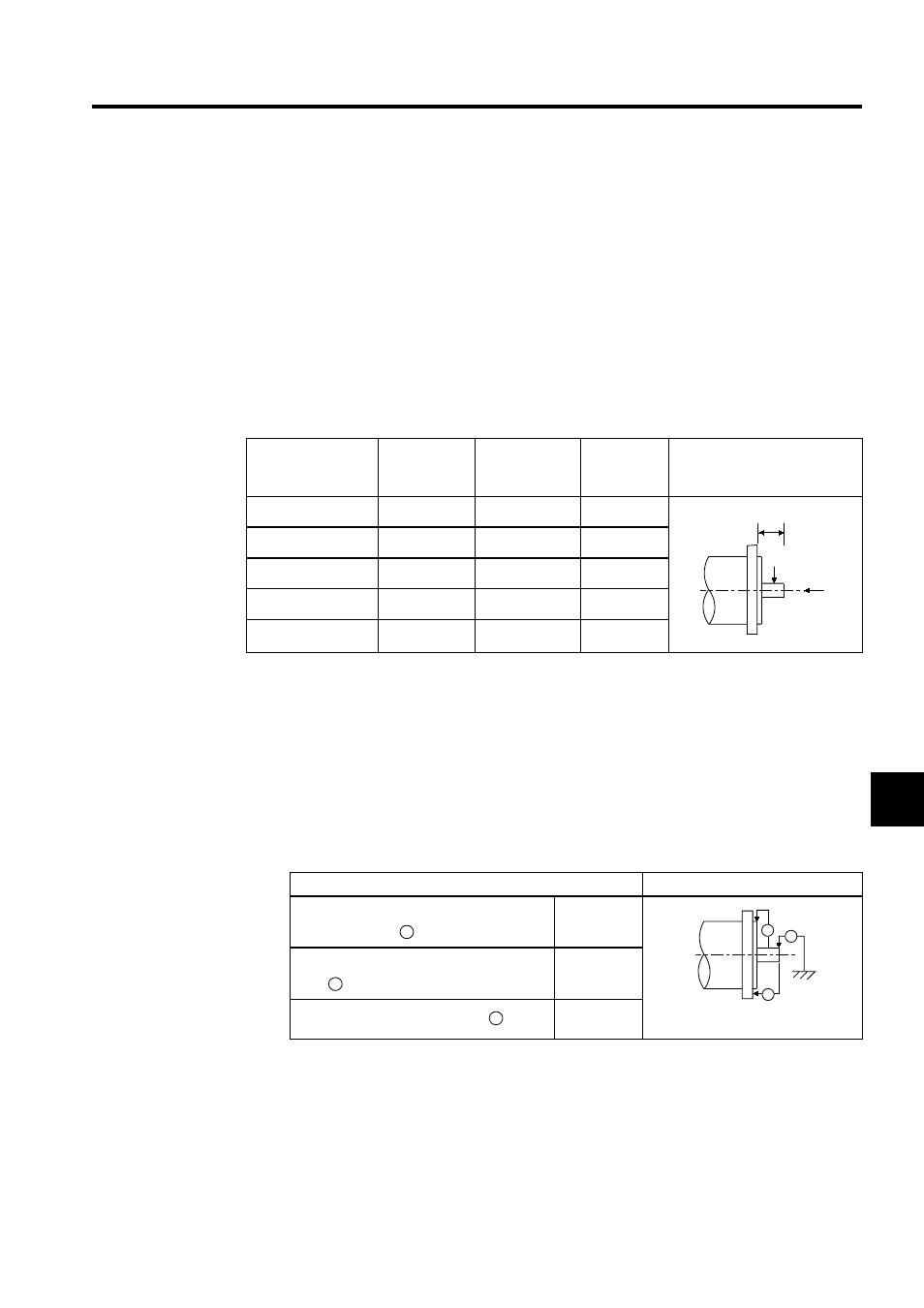
Mechanical Tolerance
The following table shows tolerances for SGMBH servomotor output shaft and installation
area. See the dimensional drawing of the individual servomotor for more details on toler-
ances.
Table 7.3 Allowable Radial and Thrust Loads for the Servomotor
Servomotor Model
SGMBH-
Allowable
Radial Load
Fr [N (lbf)]
Allowable
Thrust Load
Fs [N (lbf)]
LR
mm (inch)
Reference Diagram
2BD
5880 (1323)
2156 (485)
100 (3.94)
3ZD
6272 (1412)
2156 (485)
100 (3.94)
3GD
7448 (1676)
2156 (485)
100 (3.94)
4ED
7840 (1764)
2156 (485)
100 (3.94)
5ED
8428 (1897)
2156 (485)
110 (4.33)
Fr
Fs
LR
Tolerance T. I. R. (Total Indicator Reading)
Reference Diagram
Perpendicularity between the flange face
and output shaft
0.05
Mating concentricity of the flange
O.D.
0.05
Run-out at the end of the shaft
0.03
)
A
B
C
*
+