8 using the near output signal – Yaskawa Large Capacity Sigma II Series User Manual
Page 156
4 Parameter Settings and Functions
4.5.8 Using the Near Output Signal
4-80
4.5.8 Using the Near Output Signal
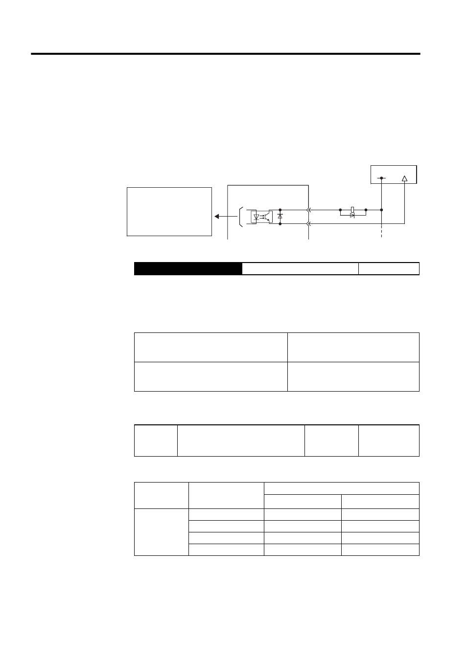
The basic use and wiring procedures for the near (/NEAR) output signal (photocoupler out-
put signal) are described below. The signal is a sequence signal that is generally output
together with the positioning completed signal (/COIN), and it is used to indicate the servo-
motor is close to completing operation.
Note: *1 and *2 are the output terminals allocated with Pn510.0.
The SERVOPACK receives the near signal before the host controller checks the positioning
completed signal and prepares the following sequence signal in order to reduce the number
of operations required to complete servomotor operation during position control.
To use the /NEAR signal, an output terminal must be allocated using the parameter below.
Pn510.0 is used to allocate the /NEAR output signals above.
Note: Multiple signals allocated to the same output circuit are output using
OR logic. Set other output signals to a value other than that allocated
to the /NEAR signal in order to use the /NEAR output signal alone.
See 4.3.4 Output Circuit Signal Allocation.
Output
→ /NEAR
Near Output Signal
Position Control
ON:
Closed or low level
The servomotor is close to completing oper-
ation. (Position error is below the near sig-
nal setting range.)
OFF:
Open or high level
The servomotor is not close to completing
operation. (Position error is above the near
signal setting range.)
Setting: Pn504 (near signal width)
Pn510
Output Signal Selections 3
Factory
Setting:
0000
Position Control
Parameter
Setting
Output Terminal (CN1-)
∗
1
∗
2
Pn510.0
0
-
-
1
25
26
2
27
28
3
29
30
SERVOPACK
Photocoupler output
(per output)
Maximum operating voltage:
30 VDC
Maximum output current:
50 mA DC
I/O power supply
CN1-∗1
CN1-∗2
/NEAR+
/NEAR-
+24 V
0V