Yaskawa Large Capacity Sigma II Series User Manual
Page 134
4 Parameter Settings and Functions
4.3.4 Output Circuit Signal Allocation
4-58
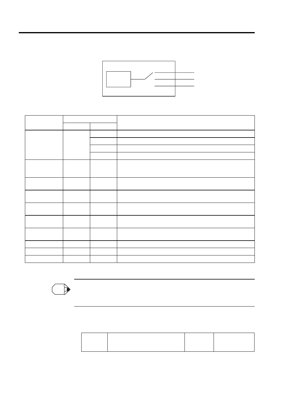
Select the CN1 connector terminals that will output the signals.
Note: “Same as above” means output signals are disabled or allocated to output terminals SO1 to
SO3 through parameter settings 0 to 3.
Multiple signals allocated to the same output circuit are output using OR logic. Signals that are not
detected are invalid. For example, the positioning completed signal /COIN is invalid in Speed Control
Mode.
The following parameter can be used to reverse the signals output on output terminals SO1
to SO3.
1
2
3
SO1(CN1-25,26)
SO2(CN1-27,28)
SO3(CN1-29,30)
Output
signal
Pn50E.
to Pn510.
Output Signal
Parameter
Description
Number
Setting
Positioning
Completed
(/COIN)
Pn50E.0
0
Disabled (Not used for the output signal on the left.)
1
Outputs the signal on the left from the SO1 (CN1-25 and 26) output terminal.
2
Outputs the signal on the left from the SO2 (CN1-27 and 28) output terminal.
3
Outputs the signal on the left from the SO3 (CN1-29 and 30) output terminal.
Speed Coinci-
dence Detection
(/V-CMP)
Pn50E.1
0 to 3
Same as above.
Rotation Detec-
tion(/TGON)
Pn50E.2
0 to 3
Same as above.
Servo Ready
(/S-RDY)
Pn50E.3
0 to 3
Same as above.
Torque Limit De-
tection (/CLT)
Pn50F.0
0 to 3
Same as above.
Speed Limit De-
tection (/VLT)
Pn50F.1
0 to 3
Same as above.
Brake Interlock
(/BK)
Pn50F.2
0 to 3
Same as above.
Warning (/WARN)
Pn50F.3
0 to 3
Same as above.
Near (/NEAR)
Pn510.0
0 to 3
Same as above.
Not used.
-
-
-
Pn512
Output Signal Reversal Settings
Factory
Setting:
0000
Speed/Torque
Control,
Position Control
INFO