A.4 output signal selections – Yaskawa Large Capacity Sigma II Series User Manual
Page 396

A.4 Output Signal Selections
A-13
A
A.4 Output Signal Selections
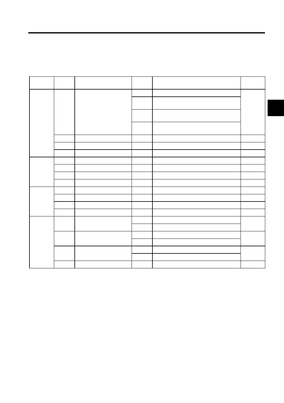
The following list shows output signal selections and their factory settings.
Note: 1. When more than one signal is allocated to the same output circuit, data is output using OR
logic.
2. Depending on the control mode, undetected signals are treated as OFF. For example, in
the speed control mode, the /COIN signal is treated as OFF.
3. Types of /WARN signals: Overload and regenerative overload.
Parameter
Digit
Place
Name
Setting
Contents
Factory
Setting
Pn50E
0
/COIN Signal Mapping
0
Disabled.
1: SO1
1
Outputs from the SO1 (CN1-25, 26) output ter-
minal.
2
Outputs from the SO2 (CN1-27, 28) output ter-
minal.
3
Outputs from the SO3 (CN1-29, 30) output ter-
minal.
1
/V-CMP Signal Mapping
0 to 3
Same as above.
1: SO1
2
/TGON Signal Mapping
0 to 3
Same as above.
2: SO2
3
/S-RDY Signal Mapping
0 to 3
Same as above.
3: SO3
Pn50F
0
/CLT Signal Mapping
0 to 3
Same as above.
0: Not used
1
/VLT Signal Mapping
0 to 3
Same as above.
0: Not used
2
/BK Signal Mapping
0 to 3
Same as above.
0: Not used
3
/WARN Signal Mapping
0 to 3
Same as above.
0: Not used
Pn510
0
/NEAR Signal Mapping
0 to 3
Same as above.
0: Not used
1
Reserved
0 to 3
Same as above.
0: Not used
2
Not used.
0
-
0
3
Not used.
0
-
0
Pn512
0
Output Signal Reversal for
SO1 (CN1-25 and 26)
0
Output signal not reversed.
0: Not
reversed
1
Output signal reversed.
1
Output Signal Reversal for
SO2 (CN1-27 and 28)
0
Output signal not reversed.
0: Not
reversed
1
Output signal reversed.
2
Output Signal Reversal for
SO3 (CN1-29 and 30)
0
Output signal not reversed.
0: Not
reversed
1
Output signal reversed.
3
Not used.
-
-
0
