3 allowable radial and thrust loads – Yaskawa Large Capacity Sigma II Series User Manual
Page 37
2 Basic Operation
2.2.3 Allowable Radial and Thrust Loads
2-10
• Fan Connector on Servomotor
The connector specifications for the fan on the servomotor are as follows:
* 1. Connector at servomotor is already provided.
* 2. Manufactured by Daiichi Denshi Kogyo Co., Ltd.
* 3. Waterproof.
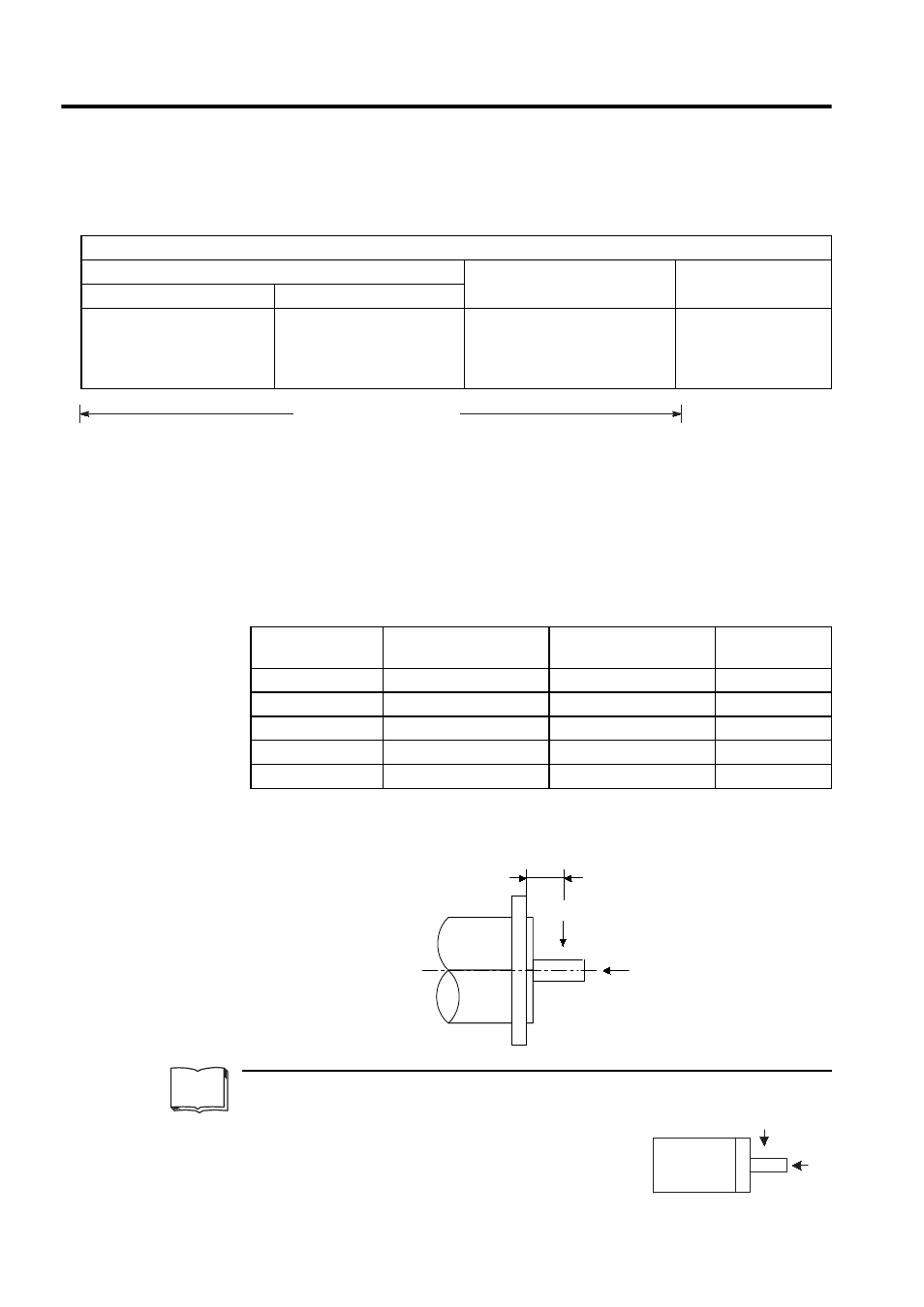
2.2.3 Allowable Radial and Thrust Loads
Design the mechanical system so radial and thrust loads
1
applied to the servomotor shaft end
during operation falls within the ranges shown in the following table.
Note: Allowable radial and thrust loads shown above are the maximum val-
ues that could be applied to the shaft end from motor torque or other
loads.
Fan Connectors
Plug
Cable Clamp
Receptacle
*1
L-shaped
Straight
CE05-8A18-10SD-B-BAS
*2,
*3
or
MS3108B18-10S
CE05-6A18-10SD-B-BSS
*2,
*3
or
MS3106B18-10S
CE3057-10A-* (D265)
*2,
*3
or
MS3057-10A
** indicates the cable diameter.
CE05-2A18-10PD-B
*3
To be prepared by the customer
1
Radial and thrust loads
Thrust load (Fs): Load applied parallel to the centerline of the shaft.
Radial load (Fr): Load applied perpendicular to the centerline of
the shaft.
Servomotor Model
SGMBH-
Allowable Radial Load
Fr [N]
Allowable Thrust Load
Fs [N]
LR
[mm]
2BD
5880
2156
100
3ZD
6272
2156
100
3GD
7448
2156
100
4ED
7840
2156
100
5ED
8428
2156
110
TERMS
Motor
Fr
Fs
LR
Fr
Fs