2 main circuit wiring and power on sequence, V power supply – Yaskawa Large Capacity Sigma II Series User Manual
Page 45
2 Basic Operation
2.3.2 Main Circuit Wiring and Power ON Sequence
2-18
2.3.2 Main Circuit Wiring and Power ON Sequence
This section shows typical examples of main circuit wiring for
Σ-II Series servo products,
functions of main circuit terminals, and the power ON sequence.
400-V Power Supply
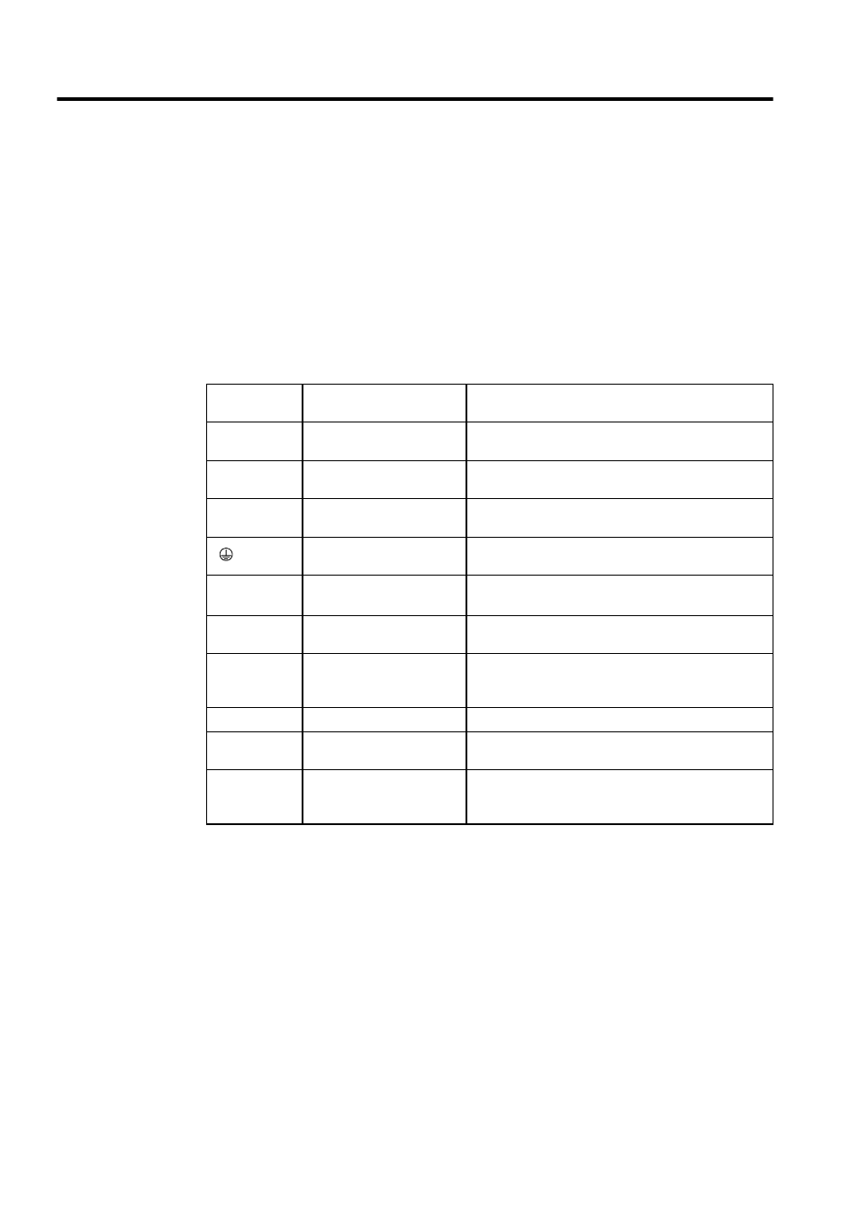
• SERVOPACK Main Circuit Terminal Names and Descriptions
The following table shows the name and description of each main circuit terminal.
Table 2.1 SERVOPACK Main Circuit Terminals
Terminal
Symbol
Functions
Description
L1/R, L2/S,
L3/T
Main power input terminals
Three-phase 380 to 480 VAC
, 50/60 Hz
U, V, W
Servomotor connection
terminal
Used to connect to the servomotor.
DC24P,
DC24N
Control power input terminal 24 VDC
±
15 %
(Two)
Ground terminal
Connected to ground.
(For power ground and motor ground)
+1, +2
DC reactor connection termi-
nal
Used to protect against harmonics
(factory setting: short-circuited)
B1, B2
Regenerative Resistor Unit
connection terminal
Used to connect the regenerative resistor.
480 V, 460 V,
440 V, 400 V,
380 V, 0 V
Input terminals for control
actuator
Single-phase 380 to 480 V, 50/60 Hz
Power supply input terminals for the fan and the contac-
tor.
−
Main circuit minus terminal
Normally, external connection is not required.
DU, DV, DW
Dynamic Brake Unit
connection terminal
Used to connect the Dynamic Brake Unit.
DBON, DB24
Dynamic Brake Unit connec-
tion terminal
Used to connect the Dynamic Brake Unit to the DBON
and DB24 terminals (when using 37-kW and 55-kW
SERVOPACKs only).
%
+10
- 15