4 speed coincidence output – Yaskawa Large Capacity Sigma II Series User Manual
Page 151
4.5 Forming a Protective Sequence
4-75
4
4.5.4 Speed Coincidence Output
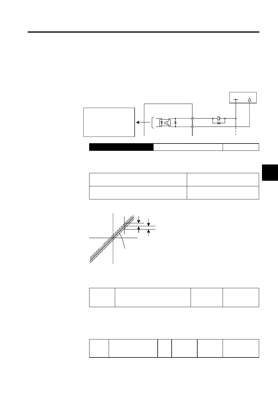
The basic use and wiring procedures for the speed coincidence (/V-CMP) output signal used
to indicate a match with the speed reference (photocoupler output signal) are described
below. The host controller uses the signal as an interlock.
This signal is output when the actual motor speed during speed control is the same as the
speed reference input.
The following parameter setting is used to change the CN1 connector terminal that outputs
the /V-CMP signal.
The parameter is factory set so the /V-CMP signal is output between CN1-25 and 26. See
4.3.4 Output Circuit Signal Allocation for more details on parameter Pn50E.
The following parameter is used to set conditions for speed coincidence output.
Output
→ /V-CMP CN1-25
Speed Coincidence Output
Speed Control
ON:
Circuit between CN1-25 and 26 is
closed, and CN1-25 is at low level.
Speed coincides.
(Speed error is below the setting.)
OFF:
Circuit between CN1-25 and 26 is open,
and CN1-25 is at high level.
Speed does not coincide.
(Speed error is above the setting.)
Preset value: Pn503 (Speed Coincidence Signal Output Width)
Pn50E
Output Signal Selections 1
Factory
Setting:
3211
Speed Control
Pn503
Speed Coincidence Sig-
nal Output Width
Unit:
min
-1
Setting
Range:
0 to 100
Factory
Setting:
10
Speed Control
SERVOPACK
Photocoupler output
(per output)
Maximum operating voltage:
30 VDC
Maximum output current:
50 mA DC
I/O power supply
CN1-25
CN1-26
/V-CMP+
/V-CMP-
+24 V
0 V
Motor
speed
Reference speed
/V -CMP is output in this
range.
Pn503