2 troubleshooting 8-41 – Yaskawa Large Capacity Sigma II Series User Manual
Page 380
8.2 Troubleshooting
8-41
8
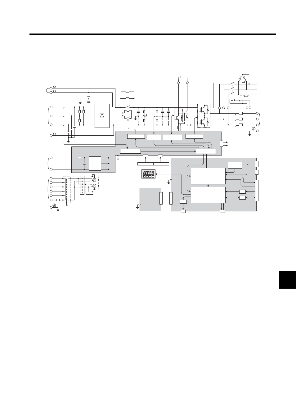
37 kW for 400 V
Fig. 8.2 SERVOPACK Internal Connection Diagram of 37 kW for 400 V
ASIC
CPU
D/A
A/D
I/O
CN5
CN3
CN10
CN2
CN8
CN1
1PCB
2PCB
+
-
+5V
+24V
+15V
43CN
3PCB
DC24P
DC24N
DV
DU
DW
MC
DCCT1
DB24
DBON
W
V
U
W
V
U
DCCT2
DCCT3
DB24
DBON
R
T
S
+
-
+
-
+
-
+
-
TRM1 to TRM6
TRM4
+
-
+
-
CHARGE
MC1
MC1
R1
200 VAC
DM1 to DM3
C64
C65
C61 C63
L1/R
1
2
-
L2/S
L3/T
B1
B2
+
+
FU1
FU4
FAN1
215V
1
2
3
4
480V
460V
440V
400V
380V
0
600V 4A
0
E
FAN2
5
6
200 VAC
SA1 ¡ 3
DV DU DW
MC
R2
PG
DC reactor
connection
terminals
Main circuit
power supply
input terminals
Main circuit
negative-side
terminal
380 to 480 VAC
(24 VDC)
Control power
supply input
terminals
Ground terminal
DC/DC
converter
Relay drive
Varistor
Varistor
Varistor
Voltage detection
Panel Operator
(Option Unit)
Thermostat 1
Thermostat 2
Voltage
detection
Voltage detection
gate drive
Gate drive
Interface
Analog monitor
Digital Operator
(PWM control, etc.)
(position/speed
calculation, etc.)
Voltage
detection
Regenerative
resistor
Regenerative resistor unit
connection terminals
Battery
Ground
terminal
detection
Motor
connection
terminals
Reference
pulse input
Sequence I/O
Speed/torque
reference input
C1 to C4
- Tag Generator (30 pages)
- MP3300iec (82 pages)
- 1000 Hz High Frequency (18 pages)
- 1000 Series (7 pages)
- PS-A10LB (39 pages)
- iQpump Micro User Manual (300 pages)
- 1000 Series Drive Option - Digital Input (30 pages)
- 1000 Series Drive Option - CANopen (39 pages)
- 1000 Series Drive Option - Analog Monitor (27 pages)
- 1000 Series Drive Option - CANopen Technical Manual (37 pages)
- 1000 Series Drive Option - CC-Link (38 pages)
- 1000 Series Drive Option - CC-Link Technical Manual (36 pages)
- 1000 Series Drive Option - DeviceNet (37 pages)
- 1000 Series Drive Option - DeviceNet Technical Manual (81 pages)
- 1000 Series Drive Option - MECHATROLINK-II (32 pages)
- 1000 Series Drive Option - Digital Output (31 pages)
- 1000 Series Drive Option - MECHATROLINK-II Technical Manual (41 pages)
- 1000 Series Drive Option - Profibus-DP (35 pages)
- AC Drive 1000-Series Option PG-RT3 Motor (36 pages)
- Z1000U HVAC MATRIX Drive Quick Start (378 pages)
- 1000 Series Operator Mounting Kit NEMA Type 4X (20 pages)
- 1000 Series Drive Option - Profibus-DP Technical Manual (44 pages)
- CopyUnitManager (38 pages)
- 1000 Series Option - JVOP-182 Remote LED (58 pages)
- 1000 Series Option - PG-X3 Line Driver (31 pages)
- SI-EN3 Technical Manual (68 pages)
- JVOP-181 (22 pages)
- JVOP-181 USB Copy Unit (2 pages)
- SI-EN3 (54 pages)
- SI-ET3 (49 pages)
- MECHATROLINK-III (35 pages)
- EtherNet/IP (50 pages)
- SI-EM3 (51 pages)
- 1000-Series Option PG-E3 Motor Encoder Feedback (33 pages)
- 1000-Series Option SI-EP3 PROFINET (56 pages)
- PROFINET (62 pages)
- AC Drive 1000-Series Option PG-RT3 Motor (45 pages)
- SI-EP3 PROFINET Technical Manual (53 pages)
- A1000 Drive Option - BACnet MS/TP (48 pages)
- 120 Series I/O Modules (308 pages)
- A1000 12-Pulse (92 pages)
- A1000 Drive Software Technical Manual (16 pages)
- A1000 Quick Start (2 pages)
- JUNMA Series AC SERVOMOTOR (1 page)
- A1000 Option DI-101 120 Vac Digital Input Option (24 pages)