1 examples of i/o signal connections – Yaskawa Large Capacity Sigma II Series User Manual
Page 49
2 Basic Operation
2.4.1 Examples of I/O Signal Connections
2-22
2.4.1 Examples of I/O Signal Connections
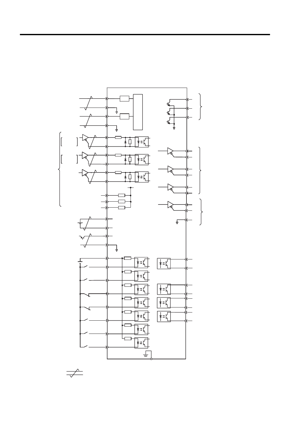
The following diagram shows a typical example of I/O signal connections.
ALO2
A/D
PULS
CW
Phase A
SIGN
CCW
Phase B
CLR
V -REF
T -REF
∗2.
∗1.
∗2.
5
10
PULS
/PULS
SIGN
CLR
11
15
12
14
+
-
+5V
0V
BAT (+)
BAT (- )
+24VIN
+24V
+
-
/S-ON
/P-CON
N-OT
P-OT
/ALM-RST
/N-CL
/P-CL
21
22
4
2
47
40
41
43
42
44
45
46
ALO1
ALO3
PAO
PBO
PCO
AO
/PBO
/PCO
/PSO
PSO
SG
/V-CMP+
(/COIN+)
/V-CMP-
(/COIN- )
/TGON+
/TGON-
/S-RDY+
/S-RDY-
ALM+
ALM -
38
39
33
34
35
36
19
20
48
49
1
∗4.
∗4.
25
26
27
28
31
29
30
32
FG
PL1
PL2
PL3
+12V
Photocouplers
Photocouplers
3
13
18
Reference speed
Torque reference
±1 to ±10 V/rated
motor torque
Open-collector
reference
power supply
Position
reference
H SERVOPACK
Alarm code output
Maximum operating
voltage
: 30 VDC
Maximum operating
current: 20 mA DC
Serial data output
Applicable line receiver
SN75175 or MC3486
manufactured by T/I or the
equivalent
Applicable line receiver
SN75175 or MC3486
manufactured by T/I or the
equivalent
Amount of phase-S rotation
Backup battery
2.8 to 4.5 V
∗3.
∗3.
SEN signal input
Servo ON
(Servo ON when ON)
P control
(P control when ON)
Reverse run prohibited
(Prohibited when OFF)
Forward run prohibited
(Prohibited when OFF)
Alarm reset
(Reset when ON)
Reverse current limit
(Limit when ON)
Forward current limit
(Limit when ON)
Speed coincidence detection
(On when speed coincides)
Positioning completed (ON
when positioning is completed)
TGON output
(ON at levels above the setting)
Servo alarm output
(OFF for an alarm)
Photocoupler output
Maximum operating voltage
:
30 VDC
Maximum operating current:
50 mA DC
Connector shell
∗
1.
∗
2. The time constant for the primary filter is 47
µs.
Connect shield to connector shell.
3. Connector when using an absolute encoder.
∗
∗
4. Used only with an absolute encoder.
SG
SG
6
9
/SIGN
/CLR
7
8
SEN
SG
/P
-
-
-
-
-
37
1 k
Ω
150
Ω
150
Ω
150
Ω
LPF
LPF
±2 to ±10 V/rated
motor speed
SGD
PG dividing ratio output
Servo ready output
(ON when ready)
represents twisted-pair wires.
3.
4.